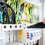
Carelabs is authorized provider of Electrical Installation’s Study, Analysis, Inspection, and Certification services in UAE, and offer protection relay testing service.
What is Protection Relay and Why Testing is Important
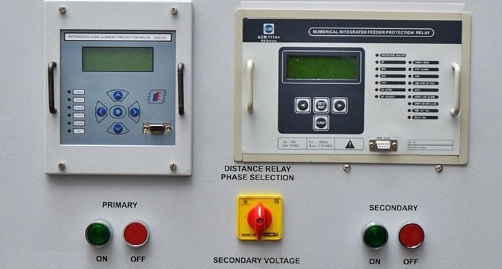
Protection relays are switches that open and close circuits electro-mechanically or electronically. Thus controlling one electrical circuit by opening and closing contacts in another circuit. Factors like Contaminated atmosphere, operating voltage, overload, insulation aging etc. affect the performance of relays.
Like the saying prevention is better than cure, the timely protection relay testing will reveal catastrophic failures which would have prevented the relay from performing when called upon to operate, and properly maintained records will reveal any trends which could lead to such failures. Periodic Maintenance Checks are required to identify equipment failures and degradation in service, so that corrective action can be taken. Because a protection scheme only operates under fault conditions, defects may not be revealed for a significant period of time, until a fault occurs. Regular testing assists in detecting faults that would otherwise remain undetected until a fault occurs.
How Protection Relay Testing is Done?
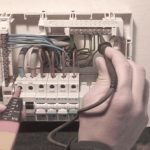
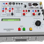
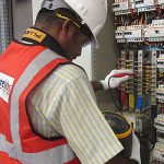
A good set of testing equipment and relay tools are used by our inspectors. Several manufacturers now produce portable relay test sets that will provided excellent results.
Following are the various steps that we perform for protection relay testing:
Visual Inspection Of Protection Relay Testing:
Before the relay cover is removed, a visual check of the cover can reveal valuable information as well as prevent possible trouble. First, of course, excessive dust, dirt or metallic material deposited on the cover should be noted and removed. Removing such material will prevent it from entering the relay when the cover is removed. The presence of such deposits may call attention to the need for some form of air filtering at the station. Included in this visual inspection should be a check for loose connections, broken studs, burned insulation, and dirty contacts. Each relay should be checked to be in agreement with its setting sheet.
Mechanical Inspection Of Protection Relay Testing:
All connections should be tight. If several connections are found loose, excessive vibration may be indicated and should be corrected. All gaps should be free of foreign material, and should excessive foreign material be found, inspection of the gasket is in order. Moving gaps (contact gaps, armature gaps, etc.) should be measured and the values compared with previous measurements. Should there be a large variation in these measurements, excessive wear may be indicated, in which case the worn parts should be replaced.
Electrical Type Protection Relay Testing:
Functional Tests
The functional tests consist of applying the appropriate inputs to the relay under test and measuring the performance to determine if it meets the specification. They are usually carried out under controlled environmental conditions.
Rating Tests
Rating type tests are conducted to ensure that components are used within their specified ratings and that there are no fire or electric shock hazards under normal load or fault condition of the power system. This is in addition to checking that the product complies with its technical specification. The following are amongst the rating type tests conducted.
Thermal Withstand
The thermal withstand of VT’s, CT’s and output contact circuits is determined to ensure compliance with the specified continuous and short-term overload conditions. In addition to functional verification, the pass criterion is that there is no detrimental effect on the relay assembly.
Electromagnetic Compatibility Protection Relay Testing:
There are numerous tests that are specified to check the working of protection relays and ability to withstand in various working environments. EMC tests determine the impact on the relay under test of high-frequency electrical disturbances of various kinds.
D.C Interrupt Test
This is a test to determine the maximum length of time that the relay can withstand an interruption in th auxiliary supply without de-energising, e.g. switching off, and that when this time is exceeded and it does transiently switch off, that no maloperation occurs.
A.C. Ripple on D.C. Supply
This test (IEC 60255-11) determines that the relay is able to operate correctly with a superimposed a.c. voltage on the d.c. supply.
D.C. Ramp Down/Ramp Up
This test simulates a failed station battery charger, which would result in the auxiliary voltage to the relay slowly ramping down. The ramp up part simulates the battery being recharged after discharging. The relay must power up cleanly when the voltage is applied and not maloperate
High Frequency Disturbance Test
The High Frequency Disturbance Test simulates high voltage transients that result from power system faults and plant switching operations.
Surge Immunity Test
The Surge Immunity Test simulates interference caused by major power system disturbances such as capacitor bank switching and lightning strikes on overhead lines within 5km of the substation.
Power Frequency Interference
This test simulates the type of interference that is caus when there is a power system fault and very high level of fault current flow in the primary conductors or the earth grid. This causes 50 or 60Hz interference to be introduced onto control and communications circuits. There is no international standard for this test.
Distance Relay Protection Relay Testing:
Consider a 110 KV overhead line. Line is protected with relays on each end. Line connects two substation a and b. using a software we can test the relays. The CMCs are connected to the relays. The Software measure voltage and current based on dynamic simulation of the network. For that the length of the KV line is measured. For a synchronised injection a gps controlled time reference simply connected to test sets using Ethernet cables. After connection is established a test shot is done and checks the performance of relays. When testing distance relays, tests should be made of pickup, angle of maximum torque, contact gap, and clutch pressure.
Directional Overcurrent Protection Relay Testing:
In addition to tests recommended for the overcurrent relay, the directional unit of the directional overcurrent relay should be tested for minimum pickup, angle of maximum torque, contact gap, and clutch pressure. A test should also be made to check that the overcurrent unit operates only when the directional unit contacts are closed.
Transformer Differential Protection Relay Testing:
There are 2 types of models for transformer differential test. After selecting necessary options for the test in the setting window of the software (like 2nd harmonic transformer vector group pick up etc). It will take us to a test group (stabilisation test, pick up test, 3 phase test etc.). Selecting the test generates corresponding results. A test of minimum pickup should be performed for differential relays. The differential characteristic (slope) should be checked, and where applicable, the harmonic restraint should be tested. Differential relays using ultrasensitive polarized units as sensing devices are slightly affected by previous history, such as heavy internal or external fault currents.
Sync Check Protection Relay Testing:
This relay monitors the voltages on both sides of a circuit breaker and determines the existence of proper phase angle and voltage before allowing the breaker to close.
Solid State Protection Relay Testing:
Unlike EMC relay where results can be obtained by a simple continuity tester. Testing with a metre won’t provide necessary load for it to turn on. Connect a load and power supply, and check the voltage of the load terminals with the input ON and OFF. The output voltage will be close to the load power supply voltage with the SSR turned OFF. The voltage will drop to approximately 1 V with the SSR turned ON. This is more clearly checked if the dummy load is a lamp with an output of about 100W. Prime causes of failure in electronic components are heat, vibration, and moisture. Overheating can be caused by voltage transients, current surges, excessive power, or high ambient temperature.
Periodic Maintenance Tests for Protection Relays
Periodic testing is necessary to ensure that a protection scheme continues to provide satisfactory performance for many years after installation. All equipment subject to gradual degradation with time, and regular testing is intended to identify the equipment concerned so that remedial actions can be taken before scheme maloperation occurs. However, due care should be taken in this task, otherwise faults may be introduced as a direct result of the remedial work.
The self-checking facilities of numerical relays assist in minimising failures due to faulty relays. Defects in secondary wiring and incorrect connections are virtually eliminated if proper commissioning after scheme installation/alteration is carried out. The possibility of incorrect settings is minimised by regular reviews of relay settings. Network fault levels change over time and hence setting calculations may need to be revised. Switching and testing errors are minimised by adequate training of personnel, use of proven software, and well- designed systematic working procedures. All of these can be said to be within the control of the user.
The remaining three causes switching errors, application shortcomings, pilot wire faults etc. are not controllable, while two of these three are unavoidable – engineering is not science and there will always be situations that a protection relay cannot reasonably be expected to cover at an affordable cost.
Although protection equipment should be in condition when first put into service, problems develop unchecked and not revealed because of infrequent operation. With digital and numerical relays the in-built self-testing routines can be expected to reveal and annunciate most faults, but this does not cover any other components that, together, comprise protection scheme. Regular inspection and testing of protection scheme is therefore required. It is desirable to carry out maintenance on protection equipment at times when the associated power apparatus is out of service. This is facilitated by co-operation between the maintenance staff concerned and the network operations control centre.


