Protective devices are equipment applied to electric power systems to detect abnormal and intolerable conditions and to initiate appropriate corrective actions. These devices include lightning arresters, surge protectors, fuses, and relays with associated circuit breakers.
From time to time, disturbances in the normal operation of a power system occurs. These may be caused by natural phenomena, by falling objects such as trees, by animal contacts or chewing; inadvertent acts by plant maintenance personnel, or other acts of humans; or by conditions produced in the system itself, such as switching surges, load swings, or equipment failures. Protective devices must therefore be installed on power systems to ensure continuity of electrical service, to limit injury to people, and to limit damage to equipment when problem situations develop. Protective devices are applied with the degree of protection desired or felt necessary for the particular system.
Why Protective Device Testing is Done?
Protection systems play a key role for the safe and reliable operation of today’s electricity power systems. Properly working protection devices help to maintain the safety of the system and to safeguard assets from damage. In order to ensure reliable operation, protective relays as well as recloser controls must be tested throughout their life-cycle, from their initial development through production and commissioning to periodical maintenance during operation.
Carelabs equipment is ideal for each of these life-cycle phases and for any environment. As a reliable long-term partner, we offer state-of-the-art testing solutions which are continuously being developed and maintained to help you to keep pace with the increasingly complex requirements of your systems.
How to Conduct Protective Device Testing?
Basic devices have the ability to recognize and define fuses, protective relays, breaker trip devices, and surge suppressors and to understand their differences and uses. A common mistake for relay testers is to use spare outputs, displays, and/or LEDs for their pickup and timing tests and ignore the in-service output logic, believing that they are using the same elements in their test equations as the final logic.
Depending on the protective device the tests varies accordingly:
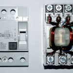
Low-Voltage Breakers
Solid-state units can be tested by either secondary or primary current injection.
The secondary injection test set allows checking of the solid state trip unit operation without using primary current. The test set will pass enough current to check any desired calibration point. The breaker must be de-energized before checking the operation of the solid-state trip units. If the test set shows that the solid-state trip unit is not functioning properly, the trip unit should be replaced.
The primary current injection method is usually preferred because this method verifies the sensors and wiring, as well as the conduction path in the breaker. It is recommended that the primary injection test be performed simultaneously on all three phases when testing breakers with solid-state trip units. If three phase primary injection testing is not practical, then the sensors and wiring should be tested separately.
These tests are performed per NETA and the National Electrical Manufacturers Association (NEMA) procedures, and in accordance with manufacturer recommendations.
Relays
A relay is an automatic device which senses an abnormal condition of electrical circuit and closes its contacts. There are different types of relays:
Current Relays
Test are made to check that the overcurrent unit operates only when the directional unit contacts are closed.
- Contact function – Contacts are manually closed (or opened) and observed that they perform their required function, i.e. trip, reclose, block, etc.
- Pickup – Gradually current or voltage is applied to see that pickup is within limits.
- Dropout or reset – Current is reduced until the relay drops out or fully resets. This test will indicate excess friction. Should the relay be sluggish in resetting or fail to reset completely, then the jewel bearing and pivot is examined.
Directional and power Relays
Directional overcurrent relaying refers to relaying that can use the phase relationship of voltage and current to determine direction to a fault.
The simplest pickup test for a directional unit is an in-phase test – i.e. current and voltage in phase. This test will eliminate the need for a three-phase supply, phase shifter, and phase-angle meter. However, it is kept in mind that such a test is usually far from the angle of maximum torque (usually 60° lag for ground relays) and thus, small changes in components can yield large variations in in-phase pickup.
Voltage Relays
Secondary Injection Test
- Measure the relay auxiliary supply to ensure it is within the nameplate rating allowable range.
- Creep or Pickup Test: Inject and reduce slowly the Red phase injector’s voltage in order to monitor and record the relay’s pickup voltage.
- Trip Time Test: Inject Red phase voltage through the relay in order to record the tripping time. Check test results against the tripping curve characteristics of the relay.
Differential Relays
A test of minimum pickup is performed. The differential characteristic (slope) is checked and where applicable the harmonic restraint is tested. Generally, differential relays are extremely sensitive devices and require some special consideration. To eliminate previous history and truly perform a maintenance test, it is the usual practice to disregard the first pickup reading and use the second reading for comparison with previous and future data.
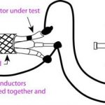
Fuses
The fuse is a reliable overcurrent protective device, primarily used as a circuit protection device for over currents, overloads and short-circuits. The idea of the test is to send a small current through the fuse; if it passes through the fuse the fuse is good. If it does not the fuse is blown and needs replacement.
Test can be done by two methods:
- Using a Continuity tester and
- Using a Multimeter
Motor Management Systems
Microprocessor-Based Motor Protection Takes Protecting and Monitoring Electric Motors into the Digital Age. Developing automated testing procedures for microprocessor relays can be classified into three categories:
- Element testing,
- Functional testing, and
- Black box testing.
The black box testing method, is adequate in terms of NERC compliance. Whether functional or black box testing, the use of dynamic testing software is the logical choice to perform the testing. Dynamic tests drive relaying test sets to run in a series of defined sequences called states-such as pre-fault, fault and post-fault. The use of element testing for microprocessor relays is likely to decline because, in part, to its noted shortcomings. The choice of functional vs. black box testing is less clear because both have their advantages and disadvantages.
One thing is clear, however, regardless of the testing method employed-documentation of testing is critical, especially if the relay application is under the NERC umbrella.
User Benefits
The technical excellence and many unique features of the Protection Device Testers translate directly into benefits for the user:
- Optimum return on investment
- Standard control unit, reduces user training
- Impulse reproducibility
- Accurate measurement system delivers information about the SPD
- Integration into existing test facilities saves engineering costs
- Pass / Fail indication for individual samples, speeds up production
- High degree of automation, reduces operator workload
- Save operator time with the automated test routines and test report facility
- Easy integration into a full test suite
- Unparalleled reliability and system up-time