Ground fault protection is the first line of defence. Once installed, ground fault protection systems stand by until needed to protect services and feeders. However, if these systems malfunction when a ground fault occurs, the distribution system and facility will be as damaged as if no systems were installed. Ground fault systems should be connected correctly and verified frequently. What is a ground fault? A ground fault is any short circuit that results in an unintended connection between an energized ungrounded phase conductor and ground. Ground faults are the most common type of fault on power distribution systems.
Why is Ground Fault Testing Required?
The National Electrical Code (NEC), Art. 230.95(C) states, “The ground-fault protection system shall be performance tested when first installed on-site. The test shall be conducted in accordance with instructions that shall be provided with the equipment. A scripted record of this test should be created and should be accessible to the authority having control.”
National Electric Code for Fault protection states that ground fault relays are meant to protect equipment from low magnitude effects that pertain to the conduction of electricity between equipment and the conducting body. There is zero assurance for gear protection against influences of larger magnitude ground faults. Protections against higher magnitude ground faults are reliant upon protective devices such as fuses and circuit breakers.
What is Done During Ground Fault Testing?
Ground fault testing procedure of current transformer includes following tests:
Testing neutral insulation resistance:
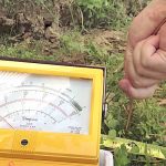
Testing the insulation resistance is crucial, as issues are generated by the grounded neutrals downside of the sensing device. The first step is to temporarily remove the neutral disconnect link. Next, measure the resistance between the neutral and ground. The value should be a minimum of 1 megohm. If the neutral is discovered to be smaller than 1 megohm, rectify the issue before putting the equipment into service. It is common practice to use an ohmmeter to take this reading. Use caution if an insulation resistance test set is used. Putting high voltage on the neutral could damage the gear tied at circuit’s downside. Replace the neutral disconnect link after testing.
Primary injection testing:
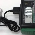
This contains inserting primary current into gear’s neutral and phase conductors to match the movement of ground-fault current under different conditions. This will establish that transformers are wired and mounted properly and that the switch or breaker wont nuisance trip under normal operating conditions. The residual sensing method and zero-sequence sensing method are the two of the most common types of ground-fault systems.
Testing reduced control voltage tripping capabilities:
Most of the ground fault schemes need control voltage to function, and most schemes have control power transformers that source the control voltage. This is beneficial as ground-fault system is an individual system that do not need an additional source to function. The shortcoming is that the control power can be decreases in the course of a ground fault; yet, the gear must be capable of operating in reduced voltage to clear the fault.
How is Ground Fault Testing Done?
Ground Fault testing procedure of circuit transformer is:
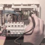
- The system performance testing as required by NEC 230.95(C) is most often required by the AHJ to be completed by a third-party electrical testing company and not by the installing contractor or owner. All testing should be done prior to energizing the device. Testing the ground-fault system requires that both the line and the load on the device being tested be de-energized. The only test that can be done on energized devices is with a secondary injection test set. Use of a secondary injection test set will test the electronics of the relay or trip unit, but does not insure the CT installation and wiring are correct. Use of the test-trip button will test the circuit within the relay or trip unit, but again does not insure the CT installation and wiring are correct. This does not meet the intent of performance testing as outlined in NEC 230.95(C). Use of the secondary test set or push-to-test button is like performance testing the safety features of a car while it is up on blocks — it may look good, but is not very effective.
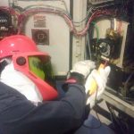
- Primary current injection by a qualified third-party testing agency using the procedure as outlined by the manufacturer is the only effective way to test the ground-fault protection systems. Testing with a primary injection test set tests the integrity of all the system components including the relay or trip unit, control power, wiring and the external CT. With primary injection testing, typically both trip and non-trip tests are used to prove the polarity of the CTs or sensors and the wiring of the system. When a system requiring control power is tested, a reduced voltage test is also done to insure the system will trip even if the supply power has lost a phase. Many ground-fault systems require particular attention to the wire that is to be used. Some require minimum sizes of conductors, shield conductors or twisting together of the conductors when connecting to the CT. Verification that the polarity of the CT is correct is most often very difficult because of the location of the CT.
- Since the control power for the ground-fault system is most often a tap conductor on the line side of the overcurrent device, this may commonly be some type of disconnect device with a fuse block. This device is the control power for the ground-fault relay and should be confirmed to be in the “on” or “energized” position. Our field personnel have opened control cabinets to several systems in operation and found them in the “off” position. At that point, there is no way to know if it was never turned on, or if it was turned off at some point to cover up nuisance tripping or some other issue in the electrical system. If the control power is not provided to an external system, there will be no ground-fault protection. If the ground-fault system is purposely disabled and someone is injured, there could certainly be grounds for litigation.
- Because the third-party ground-fault protection performance testing is often done prior to the connection of the conductors, careful examination of the CT should be made once the conductors are pulled through the CT. Is there damage to the wiring or to the CT during installation of the conductors? Do all the conductors pass through the CT, and do they pass in the correct direction and all in the same direction? The grounding electrode conductor or equipment grounding conductor should not pass through the CT. This often causes nuisance tripping, and may prevent the device from accurately tripping at the device setting. If there are questions, the system should be reviewed, repaired and retested.
- Verify that the grounding system is complete. The grounding system is the return path for a system fault. Is the grounding electrode conductor landed in the correct position and in the correct structure? Are the other systems properly grounded and bonded to provide a complete grounding system?
- Review the connection of neutral conductors at each point in the system to insure they are not grounded downstream of the neutral bonding jumper. This is often verified when the ground fault performance test is done but is mostly performed when the electrical distribution system is still unfinished, so vigilant concentration should be observed to ensure the system will work correctly. Grounding of the neutral conductor most often makes the ground-fault protection system ineffective during a system ground fault condition.
With the greatest percentage of electrical faults being phase-to-ground, the properly operable ground-fault protection system cannot only minimize damage to electrical equipment, but can also help to minimize the danger to personnel. Vigilant inspection of the ground-fault system is vital and needs a lot more concentration than just examining for a sticker.

