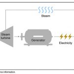
Carelabs is authorized provider of Electrical Installation’s Study, Analysis, Inspection, and Certification services in UAE, and offer lightning arrester testing service.
Lightning Arrester is the device used to protect the insulation and conductors from damaging effects of lightning on electrical power systems and telecommunication. Typical lightning arrester has a high-voltage terminal and a ground terminal. When a lightning surge travels along the power line to the arrester, electricity from the surge is diverted through the arrester to the earth.
If protection fails or is absent, lightning that strikes the electrical system introduces thousands of kilo volts that may damage the transmission lines, and can also cause severe damage to transformers and other electrical or electronic devices.
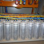
Monitoring Total Leakage Electricity
Presently the monitoring of total leakage electricity (capacitive and resistive currents) used by many utilities. The Leakage Electricity Monitor is used to measure the Leakage Current of Surge Arrester, and in case of high leakage current Surge Arrester is replaced. However, it is felt that this method is not the fool proof method as the total leakage current, which is purely capacitive, does not signify precisely the health of the Surge Arrester. There are the issues once the Surge Arrester has blasted even though total leakage current value was lower than the limit recommended by the manufacturers.
Resistive current is 15-30% of total current and since capacitive and resistive currents are at 90 degree face shift even reasonable change of resistive electricity results in very small increase in the total current. Hence observing total leakage electricity may not show degradation of ZnO disc. Degradation of long linear ZnO disc generally leads to harmonics in the leakage current when system voltage of fundamental frequency applied. Third consonant resistive electric measurement based on filtering of third harmonic element from the total leakage current. Leakage current of the order of about 500 micro amps is generally considered as safe.
The power loss can be checked by several methods given below:
- Using a voltage signal as reference
- Compensating the capacitive element by using a voltage signal
- Capacitive compensation by combining the leakage current of the three phases
- Third order harmonic analysis
- Direct determination of the power losses
- Third order harmonic analysis with compensation for harmonics in the voltage
Advance Monitoring System with Resistive Current Element calculations
The use of advanced diagnostic methods greatly decreases the chances of failure & avoids loses of man and money. It is desirable to check condition of Surge Arrester at regular time intervals, by measuring the resistive element of the continuous leakage current in service without decreasing energy of Arrester. Reliable measurements achieved by the instruments based on the principle of “Voltage Signal” as a reference. Regular monitoring of Lightning Arrester has prevented many failures in 66 kV to 765 kV substations. Advanced machineries promote testing even the Surge Arrester is in service, analysing with special current clip-on transformer leakage electricity in the Surge Arrester ground connection. The values of this current normally ranges from fractions of mille ampere to a few mille amperes entire characterized by a resistive current variations whose value is an indicator of deterioration of the Surge Arrester. Leakage of electricity increases due to different stresses like declining and Arrester failures.
Lightning Protection Systems Testing
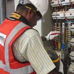
Most building services would simply not function correctly if faults or defects were present but the correct operation of a lightning protection system only becomes obvious when it called upon to protect a structure. For this reason it is even more vital to make sure that fully trained and accredited engineers undertake regular testing and maintenance works on vulnerable structures and sites.
The current in a lightning strike is likely in the range of 2,000A – 200,000A and so an effective functional system is vital to make sure protection of assets. Majority of structures use BSEN 62305 to report their design, testing and maintenance works related to lightning protection. This standard states a “competent person” should carry out inspections so a good rule of thumb is to look for contractors with third-party accreditation of their ability to design and report on lightning protections systems.
As large parts of the lightning protection system may be hidden or inaccessible after completion, it is particularly important, and indeed necessity of the code, that each element of a lightning protection system should inspect during the construction stages of an installation. Special attention must give to any part of the system that will hide conceal upon completion. These elements may hide for aesthetic reasons or the element would be necessary part of the structure. Inspections should carry out during the installation process but also upon completion and at regular intervals.
Visual inspection of an installation should take into account the following key points and observations recorded in the detailed inspection report:
- Inspections should repeat at fixed intervals, not exceeding 12 months. If the intervals fixed at 11 months, the system will inspect throughout every season of the year over 11 years
- The mechanical condition of all conductors, bonds, joints and earth electrodes should check and any observations noted
- If a part is unable to inspect, this should note.
- The bonding of any recently installed/added services should check.
This section deals with testing the earth electrodes on the system, although reference made to a visual or measured test of any joints or bonds. In practice, it is usual for inspections of components to undertake for testing to carry out.
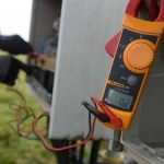
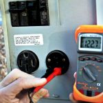
Electrode Testing Method
Electrode testing needs experience and knowledge to make sure that any test carried out is meaningful and gives back resistance of electrode under test. Too frequent, Omega handed client information presenting resistance readings that are obviously continuity tests and not true earth-resistance tests. There are two suitable methods of testing lightning protection earths: ‘Fall of Potential/the 61.8% method’ and ‘Dead Earth’. Fall of Potential recommended method and involves the electrode under test; two reference electrodes, a set of leads and four-pole test meter. The electrode under test isolated and connected to the meter shown in figure two for the ‘Fall of Potential’ or figure three for the ‘61.8%’ method. In turn, the test meter connected to the two reference electrodes, which driven nearly 300mm into the ground and located typically 25 and 50 metres away from the electrode under test.
A test made and the direct resistance of the electrode under test recorded on the meter. This method, however, is only practical if the electrode to test located near to virgin ground where test electrodes can drive. In reality, in town and city centres, this is very often not the case. Presence of buried services and pipes may also influence on the test current and the last test value may corrupt as a result of these external influences. Reference electrodes should set away from such potential disturbances. Where practical conditions dictate that the ‘Fall of Potential’ method cannot be used, the ‘Dead/Known Earth’ method is really the only practical alternative. However, it is important to aware this method is open to error and misrepresentation if the test engineer is not competent to decide suitable dead earth or interpret the readings, which is why it is essential to use an Atlas accredited engineer to undertake tests of this nature.
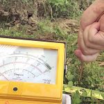
Death Earth Testing Method
The ‘dead earth’ could be any low-resistance earth not directly or fortuitously connected to the earth under test. A connection made from a suitable earth to the test meter, which is in turn connected to the electrode under test will show the lightning protection system acting as the known ‘dead/known’ earth.
A reading is then taken and the ohmic value achieved is effectively the series resistance of the electrode under test and the dead earth. The ‘Dead Earth’ method has some advantages when using the lightning protection system as the low-resistance ‘dead/known’ earth, as, due to the equipotential bonding need to other incoming services, it should give a low-resistance earth path.
Test clamps, or the clamp to the rod in the inspection pit, should open and the meter connected to the rod/rod side of the test clamp and the other side of the test meter connected to the system side of the test clamp. A reading can then be taken, which will show the series resistance of the electrode under test and the rest of the system together with other connected parallel electrical and other earth paths. As these other parallel paths usually have a relatively low combined resistance, the meter reading is effectively resistance of the electrode under test as, if correctly selected, the ‘dead’ earth that used is normally of such low value that it has little impact on final result.
In addition to providing an ohmic value for the electrode under test, this method also verifies the circuit to the dead earth source and by virtue of this, the electrical condition of the joints in the system. If the connections from the top of the test clamp to the air termination through to the other earths on the system and other parallel paths were loose or damaged, they would give a high resistance, which the meter reading would give back.
This situation should then be investigated so that any high-resistance joints can address. Where no access to an electrode is possible and, the pile foundations have utilized as the earth termination, it recommended that reference rods installed around the structure and tested upon completion. These do not necessarily form a part of the installation but may use as comparisons against the original pile foundation test results. In short, if the reference rod values have not increased year on year then it can assume neither resistance of the pile foundations.
The ‘Dead earth’ test method also applies to clamp-on CT type testers where disconnection is not needed, although this type of testing is not always practical. At least two types of test recommend one for each single electrode in isolation and a second for a combined value. The needs of BS EN 62305 are an overall system resistance (excluding bonding to any services) of 10, and each electrode not exceeding 10 times the number of earth electrodes on the system. Any disconnection of the system should carry out with a test to make sure that it is not ‘live’ and no testing should carry out during storm conditions.
Failure to keep up to date, accurate records can result in hidden parts of a system not being adequately attended to and potentially unnecessary remedial works being proposed and executed, as a full assessment of the installation has not been made. At the time of the annual test and inspection, the following records needed either on site or in an accessible place.
BSEN 62305 states that the following records should be kept:
- Drawings of the lightning protection system
- Details of the geology (nature of the soil and details of any special earthen arrangements)
- Type and place of the earth electrodes
- Test conditions and results obtained
- Details of any alterations to the system, including additions and repairs
- The name of the person responsible for the system.
In order to comply with the Construction Design and Management Regulations, these records should give at completion of the original installation for inclusion in the project Health and Safety file. The person responsible for the upkeep of the building should recover the lightning protection system records from this file and present them to the engineer undertaking the first post-installation inspection and test. Details of the inspections should record so that the needed information can updated and maintained. The programme of tests and inspections would analyse what, if any, maintenance needed. BS EN 62305 states that attention should give to the following:
- Earthing
- Evidence of corrosion or conditions likely to lead to corrosion
- Alterations and additions to the structure that may affect the lightning protection system (e.g. changes in use of building, installation of crane tracks, erection of radio and television aerials).
Ensure Lightning Protection System is Functional
Statistics show the UK alone subjected to around two million strikes per year and, to make sure your lightning protection system is functional when called upon, bearing in mind you have no way of determining when that any maintenance work should be carried out with suitable expediency.
In the hands of experienced engineers, proper testing and maintenance of lightning protection systems can become a routine, but very necessary, part of a comprehensive safety programme. At the very least the consequences of not taking a thorough approach could incur unnecessary costs but, given the destructive potential of a lightning strike, those consequences could be much worse.
All lightning protection systems and static earthen systems must inspect and test by skilled person using calibrated test equipment. By law, this should carry out in line with the relevant standards (BSEN 62305) when the installation completed and on regular basis. Therefore lightning protection testing scheduled at interval of 11 months. Over twelve years, the protection system will test under all seasonal conditions – these can significantly affect performance due to changes in resistance and other characteristics.
- Resistance testing
- Continuity testing
- Ground or soil resistivity testing
- Visual inspection
Complete lightning protection testing would make sure that all structures, key electrical and electronic installations are safe from the effect of lightning strike. You will receive a detailed report that will include not only the findings of the test but also any recommendations for further protection.
Maintenance work and upgrades are required if the testing and inspection reveals any deterioration in the level of protection or if any changes or additions to the structure rendered the existing systems inadequate.
Using the latest testing equipment, our engineers and technicians are proficient in all necessary inspection and testing process.