What is Capacitor Bank Testing and why is it done | Carelabz.com

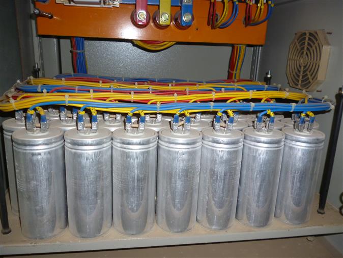
Capacitor Bank is a combination of numerous capacitors of similar rating that are joined in parallel or series with one another to collect electrical energy. The resulting bank is then used to counteract or correct a power factor lag or phase shift in an AC power supply. They can also be utilized in a DC power supply to step up the total amount of stored energy or to step up the ripple current capacity of the power supply.
Capacitor banks are generally used to
- Power Factor Correction
- Reactive Power Compensation
Capacitors have the opposite effect to the inductive motors where it cancels out a large current flow and thereby, this capacitor bank reduces your electricity bill.
Why is Capacitor Bank Testing Done?
Capacitors banks are an important aspect of your power system that provides correct power factor correction. Power Factor Correction unit have various functioning settings depending upon on the position they are installed. Moisture, time, harmonics and temperature changes the power factor correction of capacitor banks. Already installed capacitor banks, if not tested or unmaintained within specific time, becomes incapable of functioning at their finest levels. With time, the operation of capacitors can weaken, decreasing the power factor of your power system, resulting in power factor loss.
What are Done During Capacitor Bank Testing?
For checking a capacitor bank, IEEE or ANSI standard is utilized. There are 3 types of test done on capacitor banks. They are
- Design Tests or Type Tests
- Production Test or Routine Tests
- Field Tests or Pre-commissioning Tests
Design Tests or Type Tests of Capacitor Bank
When a new design of power capacitor is launched by a manufacturer, it to be tested whether the new batch of capacitor comply the standard or not. Type tests or Design tests aren’t done on single capacitor instead they are done on some casually chosen capacitors to make sure accordance of the standard.
During launching of new design, once these design tests are performed, there is no need of repeating these tests for any further batch of production until the design is changed. Design tests or type tests are usually expensive or destructive.
The type tests Performed on Capacitor Bank are –
- High Voltage Impulse Withstand Test.
- Bushing Test.
- Thermal Stability Test.
- Radio Influence Voltage (RIV) Test.
- Voltage Decay Test.
- Short Circuit Discharge Test.
Routine Test of Capacitor Bank
Routine test is also referred as production tests. These tests should be performed on each capacitor unit of a production batch to ensure performance parameter of individual.
Short Time Over Voltage Test
In this test, a direct voltage of 4.3 times of rated rms voltage or alternating voltage of 2 times of rated rms voltage is applied to the bushing stands of capacitor unit. The capacitor range must withstand any of these voltages for at least ten seconds. The temperature of the unit during test should be maintained at 25 ± 5 Degree. In case of three phase capacitor unit, if the three phase capacitor elements are connected in star with neutral connected through a fourth bushing or through casing, the voltage applied between phase terminals, would be √3 times of above mentioned voltages. Same voltage as above would be applied across phase terminal and neutral terminal.
Terminal to Case Voltage Test
This test is only applicable where internal capacitor elements of a unit are isolated from its casing. This makes sure the withstand capacity of over voltage of the insulation offered between capacitor elements and metal casing. The test voltage is applied between casing and bushing stand for 10 seconds. For the capacitor unit having bushings of different BIL, this test is done based on lower BIL bushing.
Capacitance Test
This test is done to ensure that each of the capacitor unit in a batch or lot should give not more than 110 % of its rated VAR during normal functioning within possible temperature limit which is considered as ˚C. If the measurement is done at any temperature other than 25˚C, then the meandered result should be calculated according to 25˚C.
Leakage Test of Capacitor Units
This test is done to ensure that the limit is free from any leakage. In this test the test unit is heated by an external oven, to force the insulating liquid to come out from the casing if there is any leakage point. This test makes sure that all joints are tightened and sealed correctly.
Discharge Resistor Test
This test is done on each capacitor unit to ensure that internal discharge device or resistor is capable enough to discharge the capacitor unit from its initial residual voltage to 50 V or less with in specified time limit. Initial residual voltage may be √2 times of rated rms voltage of the capacitor.
Loss Determination Test
This test is performed on each capacitor unit to demonstrate, the loss occurs in the unit during operation is less than the maximum allowable loss of the unit.
Fuse Capability Test of Internal Fused Capacitor Unit
In this test the capacitor unit is first charged with direct voltage (DC) up to 1.7 times of the rated rms voltage of the capacitor unit. Then this unit can discharge through a gap situated as closely as possible without any additional impedance to the discharge circuit. The capacitance of capacitor should be measured before application of charging voltage and after discharging the unit. The variance of these 2 measurements should be smaller than the variance of capacitance when an internal fuse element is activated.
Pre-commissioning or Installation Test of Capacitor Bank
When a capacitor bank is practically installed at site, there must be some specific tests to be performed to ensure the connection of each unit and the bank are in order and as per specifications.
Capacitance Measurement
To determine the capacitance of the bank as whole, a sensitive capacitance meter is used, to make sure the connection of the bank is as per requirement. If the measured value is not as calculated, there must be some wrong connection in the bank which to be rectified. We should apply full rated voltage for determining capacitance of a bank, instead of that only ten percent of rated voltage to find out the capacitance of the unit. The formula of capacitance is Where, V is the applied voltage to the bank, I is the supply current and ω = 377.7 which is a constant quality.
High Voltage Insulation Test
This test is done according to NBMA CP-1.
How is Capacitor Bank Testing Done?
Carry Out an On-Site Risk Assessment
- Before doing this task any threats at the site should be assessed and identified with proper control measures.
- If any hazards cannot be decreased or managed to a suitable limit, don’t continue with the task and ask for assistance from your Supervisor.
All Work to be Done with Capacitor Bank De-energized
- All the tests should be carried out with the capacitor bank de-energized and appropriate control measures in place to prevent inadvertent contact with adjacent live plant or breaching exclusion zones.
- Issue a Test Permit and follow the requirements of P53 Operate the Network Process. According to Substation Primary Plant and Secondary Systems Field Testing, safety risks applicable to capacitors include:
- Contact with high voltage at capacitor bank primary connections
- Extreme fault current
- Stored energy in charged capacitors
Carry Out Secondary Isolation
- Assess the necessities to perform secondary isolation of the protection systems.
- Consideration should be granted to the sensitivity of capacitor bank protection while making this evaluation and the potential for a capacitor under test to inadvertently discharge stored energy into a protection system.
- For majority of cases secondary isolation of the protection system would be necessary.
Record Plant DetailsRecord identification details of each capacitor unit
- Manufacturer’s name
- Manufacturer’s type description
- Manufacturer’s serial number
- Year of Manufacture
- Measured capacitance and rated Capacitance Cn as marked on the nameplate
- Serial number of each capacitor can
- Rated Output Qn
- Rated Voltage Un
- Rated Current In
- Temperature Category
Visual Inspection of Capacitor Bank Condition
- Inspect the external surfaces and ensure the capacitor units and reactors are clean and dry.
- Check that primary connections are correct.
- Check earthing to capacitor bank mounting frames and enclosure.
Measure Insulation Resistance
- Insulation resistance tests as listed below are to be applied for one-minute duration each.
- Safety CTs/VTs attached to the bank star point must be detached for these tests.
- Where several components are connected in parallel, for example capacitor cans, it is not necessary to obtain a separate insulation resistance measurement of each component.
- To make sure that capacitors being assessed have altered adequately to allocate precise IR measurement make sure that the capacitor has been charged by the megger such that there is less than a 5 % change in IR over a 1-minute period.
Measure Capacitance
- Measure the capacitance of each individual capacitor unit using a capacitance bridge. The use of any test equipment is to be performed in accordance with the operating instructions specific to the equipment being used.
- Note that tong type capacitance bridges can normally be used without disconnecting the capacitor units from the bank.
- It is favored not to dettach the capacitor units for measurement to evade unintended harm to the capacitor unit bushings.
- Note that the bushings have strictly specified maximum torque limits which must not be exceeded during tightening of connections.
- On the other hand, an AC current source must be attached to insert into a capacitor unit in series.
- The voltage measured across each unit from which the capacitance can be calculated according to the formula: **C = I / (2 x Pi x f x V)**Where C = capacitance in farads. V = induced voltage in volts. I = injected current in amps. f = frequency of injected current.
- The capacitance calculation must be done at a period when the temperature is steady across the bank.
Measure Reactance
- Where inrush limiting reactors or tuning reactors are fitted, measure the reactance of the reactors.
- The favored technique is to insert a huge alternating current and determine the voltage induced across the reactor, from which the reactance can be calculated according to the formula: Z = V / IWhere Z = reactance in ohms. V = induced voltage in volts. I = injected current in amps.
- This formula ignores the resistive component of the impedance, which is a valid simplification for typical reactors (the Q of a typical air cored reactor exceeds 40.
Carry Out High Voltage Test
- High voltage AC and DC testing of capacitors is only necessary if demanded by the owner and is usually only asked if there are manufacturing or batch issues to be solved.
- Alternatively, it may be required at the discretion of the commissioning engineer when a de-commissioned bank is being returned to service. A capacitor shall withstand a DC Test voltage applied for 10 seconds between the primary terminals.
- The voltage level to be applied is: Utest = Un x 4.3 x 0.75Where Utest = applied test voltage. Un = capacitor rated voltage.
- The capacitor shall also withstand a 1-minute power frequency withstand test of a test voltage applied between the capacitor terminals and earth.
Check Balancing of Each Bank
- Perform checking of the balance of every bank by inserting the measured capacitance amount into a proper balancing program.
- Where necessary swap cans to achieve acceptable balancing of the bank.
Carry Out Primary Injection
- Primary injection might be performed to verify functioning bank unit protection schemes by bridging out the bank capacitor cans and using a low voltage current source to inject through appropriate CTs.
- If primary injection is required to confirm that the capacitor bank balance is correct, it should be carried out at a time when the temperature is relatively stable and uniform across the bank.
- Employ a balanced three phase source into the input terminals of the bank and determine:
- The voltage applied to each phase (phase to phase and phase to neutral).
- Each phase line current.
- The voltage of the capacitor bank star points relative to neutral.
- The voltage/current measured at the out of balance protection.
- The secondary current from each metering/protection CT core.
- Confirm that any out of balance current/voltage, when scaled from the primary injection test voltage to actual rated voltage, is below the threshold required for an out of balance alarm or trip to occur.
Complete Pre-commissioning Checklist
A capacitor bank being placed in service for the first time requires that the following items are checked (if applicable) prior to energization:
- Check sheet metal work is free from transport damage and assembled correctly.
- Check that all permanently fixed panels are properly bolted in position.
- Check all door fittings are tight.
- Check door locks operate properly.
- Check overall appearance and paintwork is clean and free from scratch marks.
- Check all control cable terminations are correct and tight.
- Check capacitors are neat and free from breaks or leaks.
- Check that busbar connections have been torqued correctly.
- Check that capacitor bushing connections have been torqued correctly.
- Check earth switch operation.
- Check isolator operation.
- Check operation of discharge timers and electrical interlocking with control systems and HV circuit breakers and switches capable of energizing the bank.
- Check operation of point on wave relays, including adaptive capability of the POW relays.
- Ensure interlock system keys are provided.
- Check cubicle lighting operation.
- Check the heater operation.
- Check all fuses/links are in place.
- Check all CT secondary links are closed.
- Check external fences and gates.
- Check that all labels and nameplates are in position.
- Record asset management plant details for SAP/MIMS.
- Check operation of all control and protection functions.
Energize and Carry Out on Load Tests
- After energization save secondary currents and voltages on all protection and metering secondary circuits, including residual, phase and out of balance measurements.
- Prove and record correct operation and adaptivity of point on wave switching devices. Several test energizing may be necessary.
Benefits of Capacitor Bank Testing
- Reduce line current of the system
- Improves voltage level of the load
- Reduce system Losses
- Improves power factor of the source current
- Reduce load of the alternator
- Reduce capital investment per megawatt of the Load.
- Reduce electricity bill
FAQ
Common Questions
What are Done During Capacitor Bank Testing?
For checking a capacitor bank, IEEE or ANSI standard is utilized. There are 3 types of test done on capacitor banks. They are * Design Tests or Type Tests * Production Test or Routine Tests * Field Tests or Pre-commissioning Tests
How is Capacitor Bank Testing Done?
Carry Out an On-Site Risk Assessment * Before doing this task any threats at the site should be assessed and identified with proper control measures. * If any hazards cannot be decreased or managed to a suitable limit, don’t continue with the task and ask for assistance from your Superviso.
Get Started
Need expert support?
Carelabs delivers arc flash studies, power system analysis, and DEWA compliance services across the UAE.