Carelabs is authorized provider of Electrical Installation’s Study, Analysis, Inspection, and Certification services in UAE, and provide Contact Resistance Testing Service.
Contact resistance testing also known as Ductor testing, measures the resistance of electrical connections – terminations, joints, connectors, busbar sections or cable connections and so on. These can be connections between any two conductors, for example, cable connections or busbar sections. The instrument which is used to perform the ductor test is called an Ohmmeter, and since its function is to perform the ductor test, the ohmmeter is also known as a ductor tester.
The ductor tester can be found in many variations such as Micro, Mega and Milli- Ohmmeters, static resistance tester or DLRO which stands for Digital Low Resistance Ohm Meter. Is used to measure resistance in different applications of electrical testing. This tester consists of a DC ammeter and a few other components. The test measures the resistance at the micro- or milli-ohm level and is used primarily to verify that electrical connections are made properly, and can detect the following problems:
- Loose connections
- Adequate tension on bolted joints
- Eroded contact surfaces
- Contaminated or corroded contacts
Why You Need Contact Resistance Test?
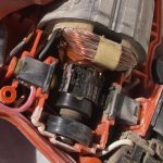
The contacts in the circuit breaker needs to checked periodically to ensure that the breaker is healthy and functional. Poorly maintained or damaged contacts can cause arcing, loosing phase, and even fire.
This test is especially important for contacts that carry large amounts of current (e.g. switchgear busbars) because higher contact resistance can lead to lower current carrying capacity and higher losses. Ductor testing is usually performed using a micro/milli-ohmmeter or low ohmmeter.
Measurement of the contact resistance helps in identification of fretting corrosion of contacts, and allows contact corrosion to be diagnosed and prevented. Increase in contact resistance can cause a high-voltage drop in the system, which needs to be controlled.
What is Done During Contact Resistance Testing?
The two common checks conducted on the contacts of a circuit breaker are the visual inspection check and the contact resistance check.
- The Visual inspection check involves examining the contacts of the circuit breaker for any pitting marks due to arcing and worn or deformed contacts.
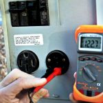
- The second check is the contact resistance measurement. This involves injecting a fixed current, usually around 100A, 200A and 300 A through the contacts and measuring the voltage drop across it. This test is done with a special contact resistance measuring instrument. Then, using Ohm’s law, the resistance value is calculated. The resistance value needs to be compared with the value given by the manufacturer. The value should also be compared with previous records.
Both these tests need to be done together. As there are cases of contacts having good contact resistance yet being in a damaged conditions. Thus, for a contact to be certified healthy, it needs to have a good contact resistance and should clear the visual inspection test.
Ductor Tester
There are two types of ductor testers in general:
- Series Type Ohmmeter has 4 resistors, internal battery voltage – E, and output terminals, A and B. When connected the A and B terminals with the R1 and R2 resistors, the battery forms a simple series circuit.
- Shunt Type Ohmmeter, used for measuring small values of current resistance. When the A and B terminals are closed, the needle reads zero because the current flows only through the resistor RX. When these two terminals are opened, there is no current flowing through the RX resistor, thus the reading on the ductor tester is marked as infinite.
How to Conduct Contact Resistance Test?
Test Criteria
The criteria for evaluating the contact resistance of electrical connections largely depends on the type of connection (e.g. bolted, soldered, clamped, welded, etc.), the metallic contact surface area, the contact pressure, etc. These will differ by equipment and manufacturer and there is no code or standard that mandates minimum contact resistances. As such, manufacturer recommendations need to be consulted. For example, manufacturers sometimes quote a maximum contact resistance of 10 micro-ohms for large bolted busbar joints.
Contact resistance measurement and its application domain are fairly extensive.
Electrical Connections
The electric connections of circuits have various ways and means, such as connected by welding, by pressing, by plug in and blot tightly and so on. To know the quality of a connector and its conduction characteristic, we just need to measure its contact resistance. The contact resistance is often applied in quality testing of switches, relays and PCB pads.
Machinery Assembly
At the aspect of the machinery assembly, the contact resistance of metals contact surface is used in estimating the reliability and tightness of the machinery assembly. The contact resistance is associated with the conduction characteristic of contact surface. The larger area and the less impurity of the pair metals surface is, the better conductivity and the lower resistance are, and vice versa.
By the ways of measuring contact resistance we can qualitatively analyse the reliability and tightness of the machinery assembly. This technique has been already applied in quality test of the shield assembly for EMC. Measurement methods for different application are not the same.
Typical Method for Contact Resistance Test
The four-wire (Kelvin) DC voltage drop is the typical method used by micro-ohmmeters for the contact resistance test, which ensures more accurate measurements by eliminating the own contact resistance and resistance of test leads.
- The contact resistance test is performed using two current connections for the injection, and two potential leads for the voltage drop measurement; the voltage cables must be connected as closer as possible to the connection to be tested, and always inside the circuit formed by the connected current leads.
- From the measurement of the voltage drop, the microprocessor controlled micro-ohmmeters calculate the contact resistance, while eliminates the possible errors due to thermal EMF effects in the connections (thermal EMFs are small thermocouple voltages which are generated when two different metals are joined together) they will be added to the total voltage drop measured, and will introduce errors into the contact resistance test if they are not subtracted from the measurement through different methods (reversal of polarity and averaging, directly measuring of thermal EMFs magnitude, etc).
- If low resistance readings are obtained when testing the breaker contact resistance using a low current, then we re-test the contacts at a higher current. Why would we benefit using a higher current? A higher current will have the ability to overcome connection issues and oxidation on terminals, where a lower current may produce false (higher) readings under these conditions.
It is very important in the contact resistance test to maintain consistent measurement conditions, to be able to compare with previous and future results for trending analysis. Therefore, when taking periodic measurements, the contact resistance test must be performed in the same position, with the same test leads (always with the calibrated cables supplied by the manufacturer), and in the same conditions, to be able to know when a joint, connection, weld or device will become unsafe and makes
Conclusion Measurements of thermal conductivity are also subject to contact resistance, with particular significance in heat transport through granular media. Similarly, a drop in hydrostatic pressure (analogous to electrical voltage) occurs when fluid flow transitions from one channel to another.
Contact resistance tests provide information about how healthy the contacts are and their ability to handle their rated current.
The maximum contact resistance is verified against manufacturers’ specifications. Rated current should not be exceeded and testing at 10% of the rated current is recommended.
The minimum DC test current is used according to manufactures specification; however, the IEC and ANSI recommended levels are: 50 A IEC 60694 100 A ANSI.