Structured cabling is a costly affair and should be handled with care. The expense of replacement once the routes are all covered is higher. The error is not always clear as bending, crushing or kinking. Confirm with your cabling installer to make sure they have made facility to guard installed cabling from actions of other workers. This is considerably inexpensive than having to change cabling in the time ahead. If cable routes are shielded with no way of opening them between installation and termination, it is sensible to terminate the cables temporarily, so they can be tested before the routes are shielded.
Why is Cable Testing Important?
You should never take an upgraded or fresh network for granted. In the case of a fresh or developed network, you believe and await its functioning to be perfect with no delays, no lost productivity or no bottlenecks. However there are some aspects that can cause poor functioning of the networks like:
- Bad products, for example connectors, cables, etc.
- Improper system installation
Wrong installation is the criminal, most of the time, after a fresh network has been completed. Thus after a fresh installation or huge upgrade, it is vital do cable testing as a final step to ensure everything is installed correctly and that not anything will stop or slow down your network.
In certified cable testing network cable performance is matched with industry standards and the result reveals a fail or pass. This type of testing makes sure that the freshly installed network will deliver the transmission speeds you hope for.
A certified cable test can pick up on potential issues such as:
- Cable runs that are too long
- Too much cable tension
- Cable kinks or damage
- Malfunctioning cable
- Proper connector installation
- Improper termination
- Crossed wires
What is Done During Cable Testing?
Carelabs cable testing process is carried out with the help of a variety of refined equipment. We use cable testing gear and equipment that are appropriate to all kinds of cables ranging from 400V to 400 kV and all types of cable faults such as:
- Earth faults
- Phase to Phase
- Cable Damage
- Resistive faults
- Intermittent faults
- Sheath faults
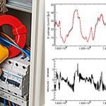
- Partial discharges
- Compare cable data with drawings and specifications. Give consideration to the cable size, number of sets, insulation rating and routing. Note these items on the test sheet.
- Inspect exposed sections of cable for physical damage. Look at the condition of the cable jacket and insulation of exposed sections. Verify that the connection points match what is shown on the project single-line diagram.
- Inspect bolted electrical connections for high resistance using with the use of a low-resistance ohmmeter, calibrated torque-wrench or thermographic survey.
- Check the state of the uncovered cable jacket and insulation when doing a visual inspection on low voltage wire and cable.
- Look at the condition of the exposed cable jacket and insulation when performing a visual inspection on low voltage wire and cable.
- Verify compression applied connections by checking that the connector is correctly rated for the installed cable dimension and has the right dents
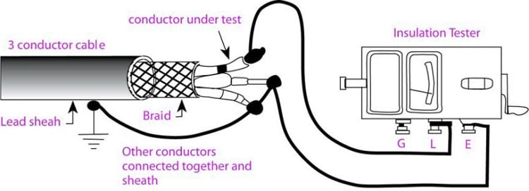
- Perform an insulation-resistance test on each conductor with respect to ground and adjacent conductors. Test duration should be for one minute utilizing a voltage in accordance with manufacturers published data.
- Verify uniform resistance of parallel conductors using a low-resistance ohmmeter. Measure the resistance of each cable individually and investigate deviations in resistance between parallel conductors.
How is Cable Testing Done?
Insulation Resistance:
- For 1 minute at 1000 Volts cables are tested with the help of megger.
- The lowest insulation resistance to earth or between phases shall be 100 megohms.
- The gear utilised for this calculation should have a low resolution of 10 megohms on the 0 to 500 megohm limit.
- In the end of Low Voltage insulation resistance testing, the neutrals should be connected to the earth rods.
Phasing Test:
- The correct phasing of all LV circuits shall be checked at all positions where the LV cables are terminated into fuse bases and where any LV cable is run from point to point.
- 240V, i.e. the main frequency voltage is unacceptable here.
- The neutral conductor shall be connected to the earth stake for this test.
Continuity Test (resistance of bolted connections):
For loop LV systems, to ensure that all bolted connections are whole and enough, a continuity test should be carried out on each LV circuit. The test is carried out as follows:
- At the transformer, firmly bond all 4 conductors together
- If there is a service provision or open point, perform a continuity test, at the furthest extent of the network.
- Any difference in the readings of neutral and each phase conductor, greater than 10% may indicate a dirty or loose connection and will require further investigation.
- The instrument used for this measurement, usually megger, should have a resolution to the second decimal point in the 0 to 5 ohm range.
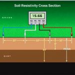
Earth Resistance Test:
- At any point along the length of a LV feeder in any overhead or underground network, the earth resistance can have a maximum value of 10 ohms prior to connection to the existing network.
- The overall resistance to earth should be less than 1 ohm prior to connection to the existing network, in any overhead or underground network.
For 11 KV AND 33 KV XLPE Cables:
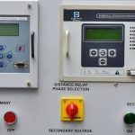
Phasing Test
- At all points where the HV cables have been ended, correct phasing of high voltage circuits should be checked.
- The test may be conducted on either the wire screens or the aluminium conductors. 240V, i.e. the main frequency voltage is unacceptable here.
- Wires should be disconnected from earth, where the test is performed.
Outer Sheath Insulation Resistance:
- The purpose of the test is to determine soundness of the outer polyethylene sheath against water ingress, mechanical damage and termite attack.
- Measure less than 0.5 megohms can show sheath damage. Values between 1.0 and 10 megohms may not indicate damage in a single location. Fault finding can often be very difficult. In new cables, values of greater than 100 megohms are required.
- The reliability of the outer sheath should be verified after cables have been buried by megger at 1000 Volts.
- The test shall be conducted for 1 minute between each wire screen and earth after the cable has been jointed and terminations installed.
- After repairs, the resistance of the cable should not be less than 10 megohms.
- Where HV cable circuits are cut and joined to new circuits, sheath testing must be carried out on the existing old circuit prior to joining to the new cable.
Certification:
When all the tests have been pleasingly finished, sign and date the test form. The complete test form should be filed with the appropriate job pack.