Electric Motor Testing is usually the first thing to be sacrificed when cutting back on operational expenses. But smart companies understands is that what this means for maintenance programs is millions of dollars of lost revenue through increased motor repair costs, downtime, and waste in industrial and commercial companies.
Why is Electric Motor Testing Done?
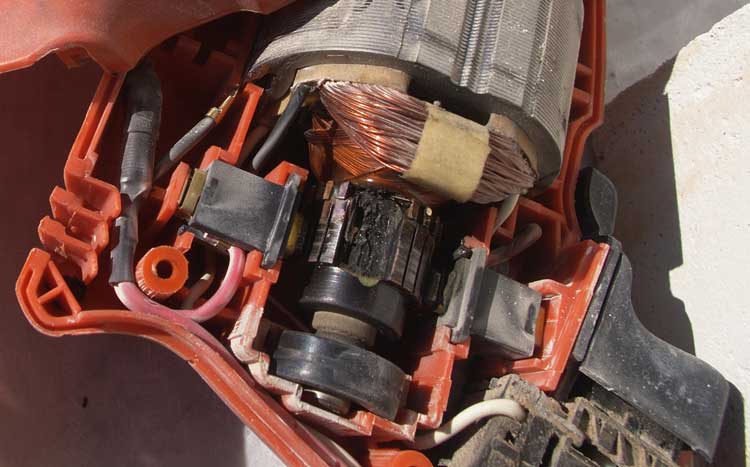
Electrical faults are the most usual means of motor failure, thus a planned electrical testing routine is crucial for safeguarding your plant reliability. Based on statistical data compiled by the Electric Power Research Institute (EPRI), 50% of motor failures are due to electrical failures. The 50% can be further broken down into rotor problems (12%) and winding problems (38%). The other 50% of failures will be mechanical faults.Winding defects can occur due to insulation age, contamination, power surges, thermal overload, damaged wire/materials, vibration, and other causes. They start as energy crossing an insulation fault, like contamination or moisture, which cuts off at least one rotation. This leads to extra stress and heat across the fault, which increases until an arc is pulled and the winding flops.
Some of the winding faults are:
- Between turns in a coil
- Between coils in a phase
- Between coils in different phases
- Between a coil or phase and ground
Removing any of the above faults can save your organisation uncountable hours of interruption and numerous dollars in savings.
What is Done During Electric Motor Testing?
There are various kinds of testing done on motor. They are:
Electric Motor Impulse Testing
Electric Motor impulse testing is an integral part of predictive maintenance of electrical motors. Through the following questions the influence that extensive impulse testing has on a motor is investigated.
- Can impulse testing harm deteriorated or healthy insulation?
- Can DC Resistance, Inductance, Megger or HiPot tests diagnose weak turn-to-turn insulation?
- After failing an impulse test, are motor with weak insulation able to operate?
- Are motors with a turn-turn short capable of continued operation? This was accomplished by putting a low voltage motor through extensive testing rigors, until inducing a failure.
Electric Motor Rotation Testing
Check for fan or pump motor rotation when testing offline with the MCE. Fans may continue to slowly rotate due to drafting in the Plenum. Pumps that are connected to a common header may continue to rotate if other pumps connected to the header are operating. This will adversely affect the Standard Test results, possibly creating higher than normal resistive and inductive imbalances.
Wound Rotor Electric Motor Testing
Wound rotor motors have a three-phase winding wound on the rotor which is connected to three phases of start-up resistors in order to provide current and speed control on start-up. Failed components in the resistor bank are common and often overlooked when troubleshooting. These faults can have a significant impact on the overall operation of the motor and should be given considerable focus when troubleshooting these motors.
Electric Motor Insulation Resistance Testing
Electric motor insulation exhibits a negative temperature coefficient, meaning as temperature increases, resistance decreases. This would lead you to believe that insulation resistance of a de-energized motor will decrease after starting the motor. However, most often the resistance will initially increase after running due to moisture being evaporated by the increasing temperature of the windings. The governing standard (IEEE43) on insulation resistance testing requires a temperature correction to 40 degrees Celsius, which could quickly turn acceptable measured resistance readings into unacceptably low corrected resistance readings. Before sending a motor to be refurbished, consider space heaters.
The recommended off-line in-service electric motor tests are:
- Stator winding resistive imbalance
- Stator winding insulation resistance (Meg-Ohm checks)
- Polarization Index (PI)
- Step Voltage test
- Surge test
The recommended spare electric motor tests are:
- Stator winding resistive imbalance
- Stator winding insulation resistance (Meg-Ohm checks)
- Polarization Index (PI)
- Step Voltage test
- Surge test
The recommended new/refurbished electric motor tests are:
- Stator winding resistive imbalance
- Stator winding insulation resistance (Meg-Ohm checks)
- Polarization Index (PI)
- Step Voltage test
- Surge test
How is Motor Testing Done?
Following are the steps for different types of motor testing:
All types
- Check the appearance of the motor. Check for body damage or damage to the cooling fan blade or shaft.
- Manually rotate the shaft to check the bearing condition. Check for free & smooth rotation.
- Note the motor data from the motor NAME PLATE.
- Earth Continuity: Use your ohmmeter to verify the resistance between earth and motor frame is less than 0.5 Ω.
- Power supply – correct voltage (230 volts per line), 415 v between Ll to L2, L2 to L3, and, L3 to L1.
Three Phase
- Ensure the terminal for power supply is in good condition. Check the connection bar for terminal (U, V and W). Connection type – STAR OR DELTA.
- Confirm the power supply VOLTAGE for electric motor. 230/400.
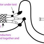
- Using the multimeter, check the continuity of winding from phase to phase (U to V, V to W , W to U ).Each phase to phase must have a continuity if winding is OK.
- Check the motor winding ohms reading using multimeter or ohmmeter for phase to phase terminal( U to V,V to W ,W to U ).The ohms reading for each winding must be the same (or nearly the same).
- Insulation resistance of motor winding using Insulation tester meter set to the 500 Volt scale (1000v DC).
1. Check from phase to phase (U to V, V to W, W to U)
2. Check from phase to earthing (U to E, V to E and W to E ). Minimum test value of the electric motor is 1 Meg Ohm (1 MΩ).
With the motor running, check the running amps of the motor using Clamp on meter.
Compare to the FLA on the name plate of motor.
If every step is completed, decide the condition of electrical motor either OK or NEED TO REPAIR.
Single Phase
- Check the motor winding ohms reading using multimeter or ohmmeter. (C to S, C to R, S to R). The reading for start to run should be equal to C to S + C to R.
- Proper recognition of electrical terminal. Common (C), Start (S) and Run (R) are the three terminal connections on hermetically sealed compressor. To identify the correct terminal connection the following procedure applies:
• The highest resistance reading is between the start and run terminals
• The middle resistance reading is between the start and common terminals.
• The lowest resistance reading is between the run and common terminals.
- Insulation resistance of motor winding using Insulation tester meter set to the 500 Volt scale. Verify from windings to earth (C to E, S to E and R to E) Minimum test value of the electric motor is 1 Meg Ohm (1 MΩ).
- With the motor running, check the running amps of the motor using Clamp on meter.
- Compare to the FLA on the name plate of motor.
- If every step is completed – decide the condition of the electrical motor: OK or NEED TO REPAIR.
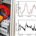
Dynamic Motor Testing
This is a current add-on to electrical testing technologies, this includes computing voltage and current of three phases of motor, while the motor is operating in its usual environment, and computing necessary data regarding the motor, power supply and load. Both electrical and mechanical issues can be identified.Power quality values, comprising unbalance, distortion and voltage level are calculated and matched with to industry standards. Bad power quality results in temperature rise within motor and as heat is the enemy of insulation, power quality problems should be pinpointed and rectified where possible.