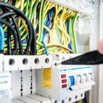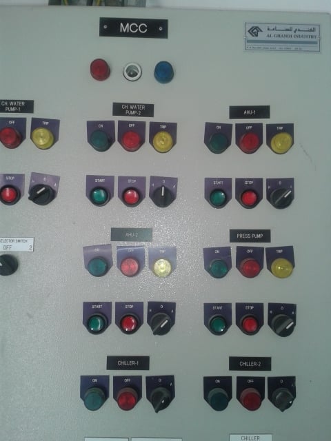
Motor control centres are just an assembly of combination starters under one roof. A combination starter is a solitary arena consisting of fuses, circuit breaker, motor starter and an instrument for cutting off power. Other equipment related to the motor like indicator lights and pushbuttons are also incorporated sometimes. These generally consists of main vertical and horizontal bus bars, incoming air circuit breakers, outgoing starter modules with MCCB or Switch Fuse Unit, contractors, overload relays etc.
Why is MCCP Operational Test Necessary?
Motor control centre panel mechanism funds opening of breaker when any errors arises such as over voltage or over current, short circuit current etc. It consists of various different relay coils, limit switches, tripping coil, motor, closing coil and also various contacts which are unified to support accurate operations. The internal operations and added facilities, which consists of various safety indicator and extra safety system differs from switchgear to switchgear. So we have control panels whose internal structural component differs along with various pin socket and different supply voltage along with separate wiring diagram.
Testing of MCCP system is one of the crucial step in the installation. Testing checks for defects at early on and makes sure correct operation of the system and also gives more consistent and secure functioning of the system. The whole operational test must be performed in order to provide supreme precision and safety.
Our engineers are experts in testing & commissioning MCC panels and our objective is to lay down the testing & commissioning necessities to be carried out on electrical installations in corporate industries and needs to be permitted from government authorities. These necessities are valid to both new installations upon completion and existing systems after huge alternations.
What is Done During MCCP Operational Test?
Insulation Resistance, Fault level withstand, continuity of conductors and earth (inc neutral earth bonds if present) conductor identification, single pole CPD’s in the phase conductors, barriers, electrical separation, current ratings and full functional testing including overload setting for motors. Add to that all labels present, paint finishes acceptable, mechanical stability as a whole and of components etc.
Testing requirements are:
- Test insulation resistance of MCC bus with a 1-minute test (phase to phase and phase to ground).
- Test insulation resistance of instrument transformers and control power with a 1 minute test at appropriate voltage.
- Test insulation resistance of contactor (closed position) with a 1-minute test (phase to phase and phase to ground).
- Test contactor contact resistance with micro-ohmmeter.
- Test reliability of every vacuum interrupter on a vacuum contactor in agreement with manufacturer’s standards.
- Calibrate and test each protective relay with settings on devices being in accordance with approved relay settings summary or coordination study.
- Test contactor drop out time if power disturbance ride through is indicated.
- Test operation of all space heaters including switching and indicating devices.
- Test CT circuit by applying current to the CT primary circuit and verifying operation of all applicable relays and metering devices.
Necessary tools are:
- Portable Hand tools
- Step Ladder
- HV Test kit
- Secondary injection kit
- Insulation resistance tester
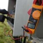
- Multimeter
How is MCCP Operational Test Done?
Pre commissioning procedure for motor control centre:
- Make sure that the MCC installation is perfect and all mechanical and electrical notes on installation ITRs are finished & approved.
- Ensure that no damage has occurred between mechanical completions & precommissioning.
- Repair/replace damage components, if any.
- Check for the location of installation is free or any water or construction debris.
- Make sure that the Motor Control Centre are correctly identified and tagged, service wise and location wise as specified.
- Ensure that the wiring termination to the Motor Control Centre are complete, tight & secure.
- Ensure that the outgoing cables, power & control from the MCC are terminated.
- Make sure that the earthing of the MCC has been executed.
- Ensure all BMS wiring has been completed.
- Ensure that the cables to the MCC are properly tagged & identified.
- Ensure that the rating of the breakers (ACB, MCCB.MCB ELCB, relays, contactors timers etc. are as per approved shop drawings & schedules.
- Ensure that overload relays are selected & set as per the actual connected load.
- Ensure that emergency stop switches are provided.
- Ensure the metering connections are proper.
- Check manually the breakers of all the cubicles in the MCC.
- Check the electrical & mechanical interlock between star & delta starters.
- Check for proper sliding of the cubicles in the rails for all draw out modules.
- Check the termination of the cables to the bus bats are tightened to the required torque using torque.
Insulation Resistance Test
- Isolate all incoming & outgoing cables.
- Apply a voltage of 500 volts Dc between phase R to earth for 1 minute with phase Y, B & N shorted & earthed & record the values.
- Repeat the test for other phases as well
Power Frequency Voltage Test
- Connect the HV lead from step up transformer to R-phase
- Short the Y & B phase and connect to earth. Also connect the enclosure to earth.
- Switch on the test kit control unit and apply the recommended test voltage (by increasing gradually) for 1 minute to R phase with respect to other phases earthed and grounded
- Record the leak current
- After 1 minute gradually reduce the test voltage to zero and then switch off the test kit. Discharge pole and also the test kit.
- Repeat the test for Y phase and B phase and tabulate the result.
Secondary Injection Test
- Verify the stiffness of secondary connections to the entire metering circuits.
- Inject the nominal secondary values step by step using secondary injection kit to the power schemes and tabulate the output values as per the ratings of meters.
Commissioning procedure for motor control center
- Make sure that all the pre-commissioning verifications are executed effectively.
- The incoming supply of the Motor Control Center shall be measured for current, voltage, frequency & phase sequence
- The outgoing feeders shall be energised one by one and the supply shall be measured for voltages
- Check the metering functions for proper operation and correct readings
- Check the functionality of starters in manual mode
- By keeping the selector switch in AUTO mode check the functionality of starters by simulation
- Check the earth leakage trip facility
- Check incomer trip setting
- Check over load relay setting
- Check timer setting