The purpose of an earthing electrical systems is to set up a mutual reference potential for the electrical conduits, cable ladders, trays etc. and the instrumentation system. To obtain this aim, proper low resistance connection to earth is necessary. However, this is hard to attain most of the time and varies according to a number of factors:
- Soil resistivity
- Stratification
- Size and type of electrode used
- Depth to which the electrode is buried
- Moisture and chemical content of the soil
The resistance of an earth electrode is related to the resistivity of the soil in which it is placed and driven, and thus soil resistivity calculations and measurements is a crucial aspect when designing earthing installations. An understanding of the soil resistivity at the planned site, and how it changes with different factors such as moisture content, temperature and depth, gives us an awareness into how the wanted earth resistance value could be obtained and sustained over the lifetime of the installation with the very less cost and sweat.
Why Soil Resistivity is Measured?
The main objective of soil resistivity testing and measurement is to attain a set of values which can be used to obtain an equivalent model for electrical performance of earth.
Soil resistivity measurements have a threefold purpose.
- This data can be used to make sub-surface geophysical surveys as an aid in identifying ore locations, depth to bedrock and other geological phenomena
- Find the degree of corrosion in underground pipelines. A reduction in resistivity means an increase in corrosion and therefore orders that a protective treatment to be used
- The design of grounding system is directly related to soil resistivity. While designing a wide grounding system, it is desirable to locate the place of lowest soil resistivity in order to achieve the most economical grounding installation
Soil resistivity completely influences the design of an earthing electrode system and is the main component that decides the resistance to earth of a grounding electrode system. So, before designing and installing a new grounding electrode system, the planned position should be tested to find out and measure soil resistivity.
What is Done During Soil Resistivity?
Sometimes the results obtained during the measurement of soil resistivity may be wrong or misleading if proper investigation is not made before the test, or if the test is incorrectly performed.
Following strategies can be used to knock off those errors
- An early research phase is necessary to offer necessary background, upon which testing programing is determined, and against which the results may be deduced
- Data related to nearby metallic structures, as well as the geological, geographical and meteorological nature of the area is very useful. For example the geographical data regarding land types and thicknesses will provide an idea about the water retaining properties of the upper layers and also the difference in resistivity to be anticipated due to water content
- By comparing recent rainfall data, against the seasonal average, maxima and minima for the area it may be ascertained whether the results are realistic or not
It has been found that special care is required when testing to:
- Eliminate mutual coupling or interference due to leads parallel to power lines. Cable reels with parallel axes for current injection and voltage measurements, and small cable separation for large spacing (>100m) can result in errors
- Ensure the instrumentation and set up is adequate (ie equipment selection criteria, power levels, interference and filtering)
- Undertake operational checks for accuracy (ie, a field calibration check)
- Reduce contact resistance (use salt water, stakes and/or the reverse Schlumberger)
- Instruct staff to use finer test spacing in areas showing sharp changes. Plot test results immediately during testing to identify such problem areas
How is Soil Resistivity Test Conducted?
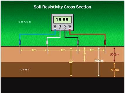
Wenner method (Wenner-4 point method):
Below are the various steps performed during Wenner Method
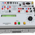
- Placed the soil resistivity measure equipment on the centre of the assessment location
- Put 2 potential electrode on the right side and left side point of view depending on the distance test needed. This electrode can be embedded upto 10 cm to ground, based on the soil condition
- Put 2 current electrode on the right side and left side point of view depending on the distance test needed. This electrode can be embedded upto 10 cm to ground depending on the state of the soil
- Connect all electrodes cable with the soil resistivity measuring equipment’s
- Boost the electrode with the power supply from soil resistance measuring equipment
- Please make sure no one touch the electrode when the electrode energize
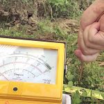
- The value of soil resistivity will appear on the soil resistivity measuring equipment’s LCD or monitor
Schlumberger Array
Following are the properties of Schlumberger array:
- Since the outer electrodes are moved 4 or 5 times for each move of the inner electrodes economy of manpower is gained with the Schlumberger array
- The reduction in the number of electrode moves also reduces the effect of lateral variation on test results
- Considerable time saving can be achieved by using the reciprocity theorem with the Schlumberger array when contact resistance is a problem
- Since contact resistance normally affects the current electrodes more than the potential electrodes, the inner fixed pair may be used as the current electrodes, a configuration called the ‘Inverse Schlumberger Array’. Use of the inverse Schlumberger array increases personal safety when a large current is injected
- Heavier current cables may be needed if the current is of large magnitude. The inverse Schlumberger decreases the bulkier cable lengths and time consumed moving the electrodes
- The minimum spacing accessible is in the order of 10 m (for a 0.5m inner spacing), thereby, necessitating the use of the Wenner configuration for smaller spacing
- Reduced voltage readings are attained when using Schlumberger arrays
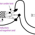
Driven Rod Method
The driven rod method (or Three Pin or Fall-of-Potential Method) are generally used in situations like transmission line structure earths, or places with difficult terrain, because of: the insubstantial; penetration that is obtained in practical situations, the restricted measurement area, and the imprecision confronted in 2 layer soil situations.
Benefits of Testing Soil Resistivity
- A perfectly designed system will perform the main role in attaining and sustaining a well-protected and professional facility
- In the fast paced competitive business world availability is everything; to stay at the forefront of hard-line business competition companies must be entirely reliable
- The ground system is an essential part of the planned site and need to be considered as highly as all the other critical components. This can be achieved with conventional methods and/or an enhanced system with electrolytic electrodes with carbon backfill and checking soil resistivity.