The field-testing and calibration of solid-state trip units can be performed by either primary current injection method or secondary current injection method. Current injection testing is generally associated with high current and high voltage power distribution systems in electricity substations or in a large industrial installations. By injecting a predetermined current into the circuit breaker, it is possible to determine whether the relay will trip at this current and, if so, how long the current needs to flow before the trip is initiated. Primary current injection testing is an invaluable aid to fault-finding.
Properties of Primary Injection Testing
- It can be done on thermal magnetic and electronic breakers
- Time intensive
- Test complete breaker from the CT, CT wiring to the trip unit, and the trip unit
- Takes more expertise to run the test
- Equipment is heavy and less portable
- More expensive
Why do We Need Primary Injection Test?
Excellent maintenance is essential for reliability and safety of power circuit breakers. Maintenance programs must be tuned to the specific application, well planned and carried out consistent with both industry experience and manufacturer’s recommendations.
Primary Injection Test is the last commissioning check to ensure that all the equipment and protection schemes are healthy and working as per the design. Connected CTs polarity is checked by Stability Test / Check which can only be carried out with Primary Injection Test.
The field-testing and calibration of solid-state trip units can be performed by either primary current injection method or secondary current injection method. The primary current injection method is usually the preferred test method because it includes the current sensors, wiring, and the current conduction path in the circuit breaker with the test. However, this method has one disadvantage in that it will not always detect sensor wiring and polarity problems.
This problem is due to the primary injection test being conducted on a single phase of the breaker at a time, whereas the solid-state trip logic of the circuit breaker functions by processing all of the signals from the three-phase sensors at the same time. In order to identify sensor- and wiring-related problems in circuit breakers, the primary current injection test should be conducted on all three phases simultaneously when testing solid-state trip units.
What is Done During Primary Injection Test?
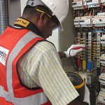
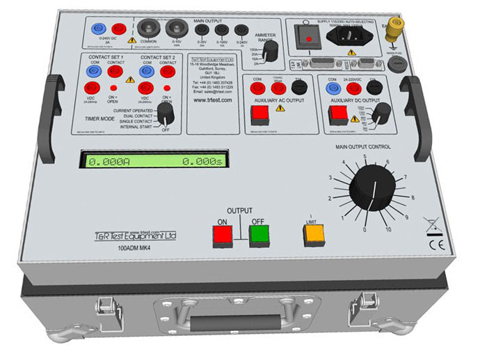
Acceptance and maintenance tests are conducted in the field using a portable primary current injection test set that is specifically designed to be more compact than factory test equipment.
Circuit breakers that have thermal-magnetic or electromechanical trip units can only be verified for correct functioning via the primary current injection test method. Circuit breakers equipped with solid-state trip devices can be tested using secondary current injection, which requires less time and expense to perform the test.
Primary current testing is conducted by injecting a programmed sequence of overload and fault magnitude currents through a circuit breaker and documenting how long it takes the trip unit to activate. When these tests are performed at a factory or repair facility, current is injected into all three poles of a circuit breaker at the same time.
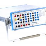
The test set has an integrated high-current transformer that supplies the simulated overload or fault current. Test sets are built with current ratings ranging from 500 to 100,000 amperes. Acceptance and maintenance tests are conducted in the field using a portable primary current injection test set that is specifically designed to be more compact than factory test equipment. These smaller test sets are generally not capable of injecting current into all three phases of a circuit breaker simultaneously.
How we Conduct Primary Injection Test?
Depending on the equipment, “Primary Injection” has different implications and can have vastly different setup requirements and measurement expectations.
Common Primary Injection Tests
Power Transformers (Through-Fault” or Thru-Fault):
- Essentially, a three-phase source (of sufficient Voltage. Current, and VA rating) is connected to a short-circuited transformer, to supply current through the windings.
- The current transformer (CT) circuits are then checked (for magnitude and angle) to verify that all test-switches and protective relays receive the proper current at the proper angle, as expected.
- Usually, the test is set up to include the high-side and low-side breakers. Often, the test is expanded to simultaneously test the CT circuits from other breakers connected to the same, or adjacent, bus.
Relay Testing
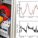
- Primary faults are simulated to check if protective relays operate correctly; trip times are measured and registered by the system, with 1 ms resolution.
- The automatic current regulation, the pre-set current injection, the injection time control, and the test results storage, gives the most advanced primary testing tool for protection relays.
Bus-work, Switchgear, and HV Breakers
- Sufficiently high current is applied to the primary conductors.
- The CT circuits are then checked (for magnitude and angle) to verify that all test-switches and protective relays receive the proper current at the proper angle, as expected.
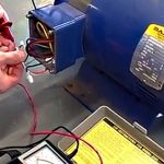
Low Voltage Breakers
- Very high (fault level) current is applied to the breaker for short duration, to measure how the Trip-Unit reacts.
- The trip-unit’s time delay is measured at various current magnitudes to verify compliance with manufacturer’s published time-current curves.
Switchgear Testing
- Low voltage switchgear and controlgear assemblies require also high current testing to comply with the relevant product standards, both by assembly manufacturers and users.
- Carelabs use devices suitable for testing the rated short-time current that the assembly must withstand, and MCB/MCCBs tripping time performance, both thermal and short-circuit trips.
Heat Runs
- With the help of amplifier-based high current generating devices, Carelabs performs heat runs, maintaining the current injection stable throughout long-term testing, and measuring the corresponding time.
Different Primary Injection Tests Done for Current Transformers
Stability Test
During commissioning the CTs may have been connected with wrong polarities. In such case, under normal condition there will be a flow of net differential current (sum of individual CT secondary current) through the relay and if this value exceeds the setting value then Differential Protection will operate to trip the breaker. Perhaps this is not expected. This commissioning mistake may be found out during primary injection test.
When primary current is flowing through the circuit, meanwhile we can check the differential current in the relay. If the differential current is zero then CT polarities are correct. But if the differential current is equal to sum of individual CT secondary current, this simply means CTs are connected with wrong polarity. We can thus take corrective action before the system becomes operational.
Loose Connection
Loose connection can easily be found if there is sparking in the connection / joint provided rated current is flowing during primary injection test. If low current is flowing during the test then it is likely to have no spark. This test is to ensure the CT circuits are properly connected with respected cores and there is no mix up in the circuit (phase identification).
Single point grounding shall be verified for CT circuits, before starting this test. Inject 25% of rated primary current between one phase and earth with all connected burden. Measure secondary current at all points of CT circuits. It shall be done for other phases.
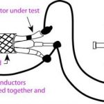
Core identification
When one CT is having several cores used for different purposes. The cores can be identified during primary injection test by shorting one of the core at CT terminal itself and check there is no current only at relevant load. The same can be verified for other cores. Inject 25% of rated primary current between phase to phase with all connected burden. Measure secondary current at all points of CT circuits. It shall be done for other phases.