The necessity for ground resistance levels are becoming stricter these days because of the smaller operating voltages and bigger operating speeds in today’s electronics. As the experts in electrical grounding solutions, we use specialized design software to model and build an electrical grounding system design based on the soil data, design goals, and other factors. After modelling the area, we will engineer an electrical grounding system design that will meet your performance objectives.
Why is Grounding System Study and Analysis Done?
The aim of grounding system analysis is to design grounding systems such that, in case of high fault currents, the acceptable levels of step and touch potentials are hedged below their maximum permissible levels and to investigate techniques, which are capable of reducing grounding resistances to the acceptable value.
Grounding keeps devices safe from surges, lightning, and faults. Few gears also need grounding as a vital component for operation, as it aids as a reference point for different measures.
The grounding system studies will detect any installation or calibration errors in your grounding system. These include things such as problems in tripping tolerance, polarity issues and neutral connections to ground. A grounding system analysis will determine if your equipment has proper ground fault protection installed and operating.
What is Done During Grounding System Analysis?
The value of body resistance is dependent on the many unpredictable factors that follow:
- Skin condition
- Touch voltage (nonlinearity)
- Touch condition
- Magnitude and duration of shock current
According to IEEE Std80-2000, the value of body resistance is usually selected as 1000Ω. Once the body resistance (Rb) and the foot resistance (Rf) are determined, both the touch and step voltage can be calculated for Rft. For the touch-voltage-equivalent circuit, the foot resistance is the parallel resistance of two feet and its value is
Rft=Rf/2
For the step-voltage-equivalent circuit, the foot resistance is the series resistance of two feet and its value is
Rft=2Rf
Two major factors that should be achieved from ground system analysis are:
Soil Resistivity
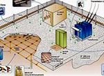
Soil resistivity testing is critical for high performance electrical grounding system design. Accurate soil resistivity data enables precise designs and predictable results. The kind of dampness, soil and temperature also influences soil resistance.
Human Safety
Human safety is critical during ground potential rise events in work place areas. Electrical grounding safety systems are required to protect personnel working where ground rise potential hazards are known to exist. In fact, federal law mandates that all known hazards must be eliminated from the work place for the safety of workers
How is Ground System Study and Analysis Done?
Step 1: Grounding system safety assessment
The electric body current provides the basis for safety assessment of grounding systems. Based on available experimental data, the IEEE Std80-2000 [1] suggests that electric body currents below Ib can be tolerated by average person. Thus according to this standard, the maximum allowable body current is:
Ib= 0.116/√tf amps
Where tf is duration of electric current in seconds.
In order to satisfy with the safety requirements of grounding systems, the maximum touch and step potential should not exceed the allowable values calculated with available equations. Thus, when it is necessary to optimize total cost of grounding systems, the computed values of touch and step potential of each desired grounding grid need to be constrained under the allowable values. Otherwise, the unqualified design of grounding systems should be abandoned.
Step 2: Electromagnetic analysis and green’s functions
The key point for analysing and optimizing grounding systems is knowing how to calculate the grounding systems safety metrics (touch potential, step potential etc.) of each specific grounding grid. Once the safety metrics are obtained, it is easy to compare them with allowable values.
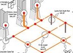
In order to calculate the grounding system parameters more accurately, it is necessary to break the underground conductors and rods into small horizontal and vertical segments. The segments may be located in either the upper or lower conducting regions. In addition, it is assumed that the fault current injected into the earth is the direct current without any calculations of inductance or capacitance and the voltage drop from one point of a grounding grid to any other point of same grid is negligible for simplicity of the model.
Step 3: Complex image method
In order to improve the efficiency of Green’s functions calculation, the complex images method has been developed to calculate the grounding systems parameters. The most significant improvement of complex images method is the implementation of finite series in place of the infinite Taylor series. The high accuracy and efficiency of the complex image method is because of the introduction of the imaginary part from image magnitude. In other words, the imaginary part brings some extra degrees of freedom
Step 4: Voltage Produced by Horizontal Lines of Current
In this, the Green’s Function solutions (point current source solutions) are used to determine of the voltages produced in the three regions due to a horizontal one-dimensional-(line) source of current located in the upper-layer or the lower-layer. The superposition theorem is employed to find the voltage in the three regions as a summation of the voltages due to a distribution of point currents, which are located on a horizontal line somewhere in the soil model.
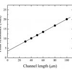
Step 5: Calculation of mutual and self-resistance
The equations for calculating the ground grid resistance to remote earth and touch/step potential are developed in terms of mutual and self-resistance of conductors. If the conductor whose induced voltage to be calculated is at a different location from the source, the potential on this conductor would vary along its length.
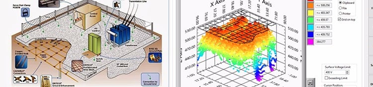
Step 6: Results compared with WINIGS
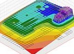
The results obtained from before are compared with WINIGS. Comparison between surface potential and self-resistance, between WINIGS and OPTIMGRID (An application developed based on the available equations) is performed.
The National Electric Code states that the resistance to ground shall not exceed 25 ohms for a single electrode. However, great technology manufacturers will often state 3 or 5 ohms, depending upon the requirements of their equipment. For delicate gear and under intense conditions, a 1 ohm reading might sometimes become necessary. When scheming a ground system, the chance of a hazard and expense grow exponentially as the target resistance to ground becomes closer to the unachievable aim of zero ohms.
Carelabs is authorized provider of Electrical Installation’s Study, Analysis, Inspection, and Certification services in UAE, and offer grounding system design and planning services.