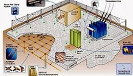
Grounding System Design and Planning starts with a site analysis, collection of geographic data, and soil resistance of the area. Generally, the site engineer or equipment manufacturers specify a resistance to ground number. The National Electric Code states that the resistance to ground shall not exceed 25 ohms for a single electrode. However, great technology manufacturers will often state 3 or 5 ohms, depending upon the requirements of their equipment. For sensitive equipment and under extreme circumstances, a one ohm specification may sometimes be needed. When designing a ground system, the risk and cost increase exponentially as the target resistance to ground approaches the unobtainable goal of zero ohms.
Grounding System Data Collection
Once a need established, data collection begins. Soil resistivity testing, geographical analysis and test borings would support grounding design. Soil resistivity test using the Wenner 4-point method suggested due to its accuracy. This method will discuss later in this chapter. Additional data always helpful and can collect from existing ground systems placed at the site. For example, driven rods at the place can test using the 3-point fall-of-potential method or an induced frequency test using a clamp-on ground resistance meter.
Grounding System Data Analysis
With all available data, smooth computer programs begin to give a soil model exhibiting the soil resistivity in ohm-meters and at various layer depths. Knowing at what depth the most conductive soil located for the site would allow the design engineer to design a system to meet essentials of application.
Grounding System Design
Soil resistivity is the important factor that regulates the resistance or execution of an electrical grounding system. It is the starting point of any electrical grounding design.
Noise Discharge Path for Grounding System
This based on extensive belief that ground systems are a kind of “cesspool” into which unwanted electrical noises safely disposed. An approach defines that noise may “accumulate” if a big discharge path is not given. This is a false concept that is not based on sound electrical principles. Literally, noise or any unwanted signal will always take the path of lowest burden, a path which at high frequencies above 1 MHz is not the SRG but other nearby cables. The concept of the SRG as a noise discharge path based on fundamental misinterpretation of grounding principles.
Electrostatic Discharge (ESD) Protection Using Grounding System
Electrostatic discharge should concern to any data centre operator due to the risk of damage to equipment. The reason of data centres are usually maintained at high humidity such as 40% relative humidity is to obstruct formation of static charges. Floors in data centres should have static discharge treatment which may include the use of special fixed or raised floor tiles. Some data centres restrict the allowable footwear to prevent group from being efficient static generators. However, the SRG has no proper role in preventing creation of static charges or protecting equipment from these charges. The SRG cannot stop group from accumulating static charge. If an operator carries a static charge, the SRG cannot stop this charge from discharged into equipment.
Human Safety by Proper Grounding System
Another generally held belief is that the SRG gives safety benefits relating to grounding and prevention of electric shock. It is genuine that proper grounding of electrical equipment is important to decrease the risk of electrical shock. It is true in 1970-1980 time periods some hard wired IT equipment in data centres was purposely wired without safety ground, to decrease noise interference. However, it is negligence of electrical codes to wire equipment without safety grounds and all pluggable equipment uses power cord that includes safety ground. Therefore, the determined ungrounding of equipment in data centres is non-existent in today’s data centre.
In a properly grounded data centre there is no problem with safety grounding that solved by the SRG. The SRG potentially give redundant safety ground, but this is not necessary or required. If unnecessary grounding system desired, it can effectively get by bonding the racks in a row to each other and running a ground wire back from the rack cabinets to the local PDU ground. Rack grounding in this way considered as “best practice” and effectively gets the same further safety benefits that SRG would give. The SRG, when properly deployed, is an unnecessary grounding system. Unnecessary grounding systems not need in the modern data centre, but even if desired there are more effective and less expensive ways to get unnecessary grounding system.
