Learn How Earth Fault Loop Impedence Testing Done | Carelabz.com
Why Earth Fault Loop Impedance Test is Done?
Every circuit must be tested to make sure that the actual loop impedance does not exceed that specified for the protective device concerned. Because of the severity of coming into contact with an electrical fault, having your electrical installations and power points tested for earth fault loop impedance is crucial. Your systems are valuable and circuitry needs to be maintained for the durability and functionality of your business. In most homes, basic shock protection is done by organising an earthing circuit with automatic switches in the indoor wiring circuits. This quickly cuts off supply to an earthing circuit where a fault occurs and touch voltage exceeds an acceptable limit.
According to the current national safety standards, you are required to conduct loop impedance test on your premises to ensure the safety of all guests and employees. The electrical earth of all your electrical installations and power points has to be tested to discover any faults within your electric circuit. Having a functional earth return circuit will allow the detection of circuit faults and facilitate a reaction from your MCB (miniature circuit breaker). Carelabs technician will detect the resistance level in your earth return circuit and notify you if it is at the wrong level – it needs to be low enough to allow the circuit breaker to function correctly. Carelabs will inspect and test your electrical wiring and by asking us to test you are protecting both your employees and your liability. It is important to adhere to national legislation to avoid harsh penalties.
The required values of impedance and time will change dependent upon the type of installation (TN/TT etc.) and the type of protection, whether it be a miniature circuit breaker (MCB), cartridge fuse or re-wireable fuse for example. The fault current can either be in the Line-Neutral or Line-Earth circuit, so there is a need to confirm the loop impedance of each
What is Done During Earth Fault Loop Impedance Testing?
It is generally accepted that, where the measured earth fault loop impedance of a circuit is not greater than 80% of the relevant limit specified in BS 7671, the impedance can be expected to be sufficiently low under earth fault conditions to meet the relevant limit specified in BS 7671, and for the protective device to automatically disconnect within the time specified.
Proper protection against electric shock hazards is given when the TT wiring system complies with:
Ra x Ia <50,
Where “Ra” is the sum of the resistances of earth bars and protective conductors and “Ia” is the maximum current of the protection system. Ra multiplied by Ia should not be more than 50 V, i.e. the maximum voltage one can touch will not exceed 50 V in the event of an earth fault.
A fault loop impedence test is done between the active conductor and the earth. To test the loop impedance our technician will use an earth loop impedence tester which is plugged into the power socket (GPO) to take a reading.
Our highly-trained staff are fully mobile and offer earth loop impedance test services across the nation.
How do We Conduct Earth Fault Loop Impedence Test?
It is recommended that the External earth loop impedance (Ze) test be done first. This test, done at the distribution board, gives the loop impedance of the circuit, excluding the installation. The system loop impedance test (Zs), which includes the circuit tested in the Ze test as well as including the installation resistance, must be done next.
AC impedance of a circuit may be different from its DC resistance – particularly for circuits rated at over 100 A – the fault loop impedance is thus measured using the same frequency as the nominal mains frequency (50 Hz).
The Ze earth fault loop impedance measurement is made on the supply side of the distribution board and the main means of earthing, with the main switch open and all circuits isolated. The means of earthing will be isolated from the installation’s earthing system (earth rods) bonding during the test. The Ze measurement will confirm the earth fault loop impedance as the sum of the resistances.
External Earth Fault Loop test sequence:
- **Step 1:**Use an Earth Fault Loop Tester or select the Earth Fault Loop Test option on a multifunctional tester such as the Megger 1553.
- **Step 2:**Test on the incoming side of the installation. Connect one test lead to the Line terminal, the second test lead to the Neutral terminal and the third (usually green) test lead to the incoming Earth conductor.
- Step 3: Press the TEST button. The measurement should be a low reading ohm value.
- Do not forget to record this value of
Zeon the Electrical Installation Certificate. - Having obtained the
Zevalue for the installation, the value ofZscan be easily calculated for every circuit.
The maximum measured earth fault loop impedance (Zs) values recorded should be compatible with the Ze + R1 + R2 value of each circuit, irrespective of the requirements of the respective protective device(s). Test results measured using low current tests are not recorded on schedules of test results, it is preferable to record the Zs values calculated from individual test results i.e.
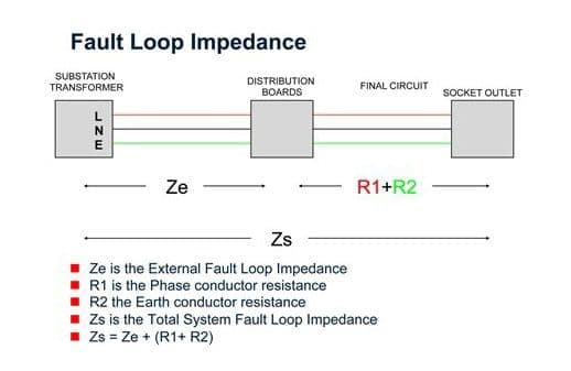
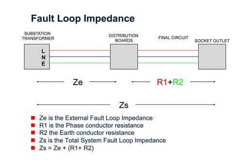
The formula for determining Zs:
Zs=Ze + (R1+R2)
Zs – earth fault loop impedance of the circuit tested
Ze – earth fault loop impedance external to the supply
(R1+R2) – Sum of the resistance of Line and Earth for the tested circuit.
Where Ze is derived from a high current test and R1 + R2 obtained during continuity testing of the circuits. The type of test results recorded and the test method used will be indicated in the appropriate remarks column of the test results schedule.
The Zs earth fault loop impedance is tested at the furthest point of each circuit. In most cases the circuit breaker needs to be bridged out. The total earth fault loop impedance is measured by plugging a loop tester into a socket outlet, or in some cases with an external earth probe. The value of the earth fault loop impedance is the sum of the resistances. When using an external earth probe, the earth fault loop impedance is measured by touching an external probe directly to an earth bar, collector and connection point of an earth bar. The same measurement can be done by touching the earth probe to exposed, conductive parts of equipment in the circuits and exposed metal parts.
The Earth Fault Loop Test Sequence:
**Step 1:**Locate the furthest point on the circuit to be tested (such as the furthest socket)
**Step 2:**With the appropriate Earth Fault Loop Tester, connect the test leads to the Line, Neutral and Earth terminals.
**Step 3:**Measure and write down the test results on the Schedule Of Test Results.
If the circuit is RCD protected than you will have to select the “No trip” function of the Megger 1553 to avoid nuisance tripping of the RCD. If your tester does not have this option then you will have to link out the RCD.
Having obtained the value of Zs for every circuit, you will be expected to verify that these values are within the accepted limits described by BS 7671.
Loop Impedance Tests Methods
As it stands today, most contractors will use one of 5 different test techniques when loop impedance testing:
- 2-wire high current test
- 2-wire “No-Trip” dc saturation test (Obsolete)
- 3-wire “No-Trip” test
- 2-wire “No-Trip” test
- 4-wire grid impedance test
2-wire high current test
This is the traditional loop impedance test. Using a test current of up to 20 A and a simple 2 wire connection, it is by and large the fastest, most accurate test available on a day to day basis. Most standard loop impedance testers will incorporate this type of test. Because of the relatively high test current, the readings are not generally influenced by external factors and will return repeatable, stable readings in most scenarios.
2-wire “No-Trip” dc saturation test
A DC test current was injected in to the circuit prior to carrying out a standard 2 wire high current test. The aim of this DC test was to saturate the monitoring coil within the RCD, allowing enough time for the high current AC test to be carried out. However, due to the increase in electronic RCDs, this method now has limited applications
3-wire “No-Trip” test
This test method overcame the need to by-pass even the new electronic protection devices by utilising a low current Line-Earth test current, whilst still returning a degree of accuracy. Not having to by-pass the RCD/RCBO obviously introduced a time saving factor. In addition, by having the requirement of connecting to Line, Neutral and Earth, the testers were now able to confirm the presence of all three as well as indicate if there was a reverse polarity at the test point and, due to the limited test current, there was no issue with tripping the MCB.
2-wire “No Trip” test
They allow testing most RCDs and RCBOs without having to bypass them. With no neutral connection required, they maintain a true 2-handed operation, but will no longer indicate reverse polarity or warn of a missing neutral. Although the physical test time is similar to that of the 3-wire method, the time saving of not having to bypass the RCD still makes for a more efficient test.
4-wire grid impedance test
The test uses a 4 wire Kelvin connection, negating internal lead and contact resistance; such is the accuracy of the test. With test currents up to 1000 A, measurements down as low as 10 MOhm can be accurately made. Consequently, there is no “No-Trip” option with this test method. With specific applications being measurement in sub-station/switch room environments, this tester gives the test engineer the ability to take accurate readings.
A circuit protected by an RCD will need special attention, because the earth-fault loop test will draw current from the phase which returns through the protective system. Thus testing of circuits protected by RCDs has presented instrument manufacturers’ with difficulties in providing test results similar to that of the testing of non-RCD protected circuits, without tripping the RCDs during the tests. Therefore, any RCDs must be bypassed by short circuiting connections before earth-fault loop tests are carried out. It is, of course, of the greatest importance to ensure that such connections are removed after testing.
At Carelabs we use an earth loop impedence tester that will not trip out the circuits RCD that we are testing. Our team will conduct all tests and inspections according to the current safety standards. Testing is mandatory for the safety of all employees. Get tested today to make sure your workplace is safe – we’re here to assist with all your compliance requirements
Since the test result is dependent on the supply voltage, small variations will affect the reading. Thus, the test should be repeated several times to ensure consistent results. Anyone on site must avoid shock hazard while establishing contact and while doing the test. When buying a loop tester ask for distribution board test leads so that Ze and Zs measurements can be done.
Impedence value:
Earth Fault Loop Impedance Testing and Recording Earth fault loop impedance testing is carried out on a completed electrical installation to check compliance with BS 7671 (IET Wiring Regulations) with regard to fault protection and is normally carried out as follows:
- With a test current of approximately 23A where circuits are protected by overcurrent devices such as fuses or circuit breakers only; or
- With a test current of approximately 15mA, to prevent unwanted tripping where circuits are protected by 30mA or other RCDs.
Typically test results for high current (23A) tests in the range 0.1Ω to 1.0Ω are largely stable with a resolution of 0.01Ω. For low current (15mA) tests the resolution was 0.1Ω, but attempts to decrease this to 0.01Ω have been largely unsuccessful in providing the same stable results for readings of less than 1.0Ω.
A recent study by one of the UK leading instrument manufacturers using instruments from seven different manufacturers under controlled conditions found significant discrepancies in the instrument readings. Further investigation revealed that the problem appeared to be mainly with the low test currents, caused by variations in power supply quality created by voltage magnitude, transients, harmonics etc. Similar tests carried out using a stabilised power supply with a clean 50Hz waveform produced more consistent results. It should however, be noted that these discrepancies, usually in the order of 1.0Ω or less, are not significant in terms of the correct operation of an RCD.
After testing is complete, we will give you a retest date (for your next earth loop impedance test) that complies with the national standards. When the time comes, our team will notify you of the retest. All results will be documented in a detailed report that is supplied to each client. Within this report, your equipment will be assigned either a pass or a fail. This document will be kept on file should you need to access it in the future for compliance verification. We provide a wide range of inspection and testing services to clients so that you can secure your entire workplace in one visit. After you’ve had your impedance test, we can provide you other inspection services too. With such a wide variety of services, there’s no reason to go elsewhere for your safety testing requirements.
Earth fault loop impedence testing is a way of insuring that you have made an electrically safe ground connection having a suitably low residual resistance. Earth loop impedance testing is essential since if a live conductor is accidentally connected to an earth conductor in a faulty appliance or circuit, the resulting short-circuit current to earth can easily be high enough to cause electric shock or generate enough heat to start a fire. Normally, the fuse will blow or another circuit protection device will trip, but a situation may arise where the actual short-circuit current in a faulty installation is of insufficient level and the protection device would thus take too long to activate. The delay can be disastrous for life and property. It is therefore necessary to know if the impedance of the path that any fault current would take is low enough to allow sufficient current to flow in the event of a fault and that any installed protective device will operate within a safe time limit.
Get Started
Need expert support?
Carelabs delivers arc flash studies, power system analysis, and DEWA compliance services across the UAE.