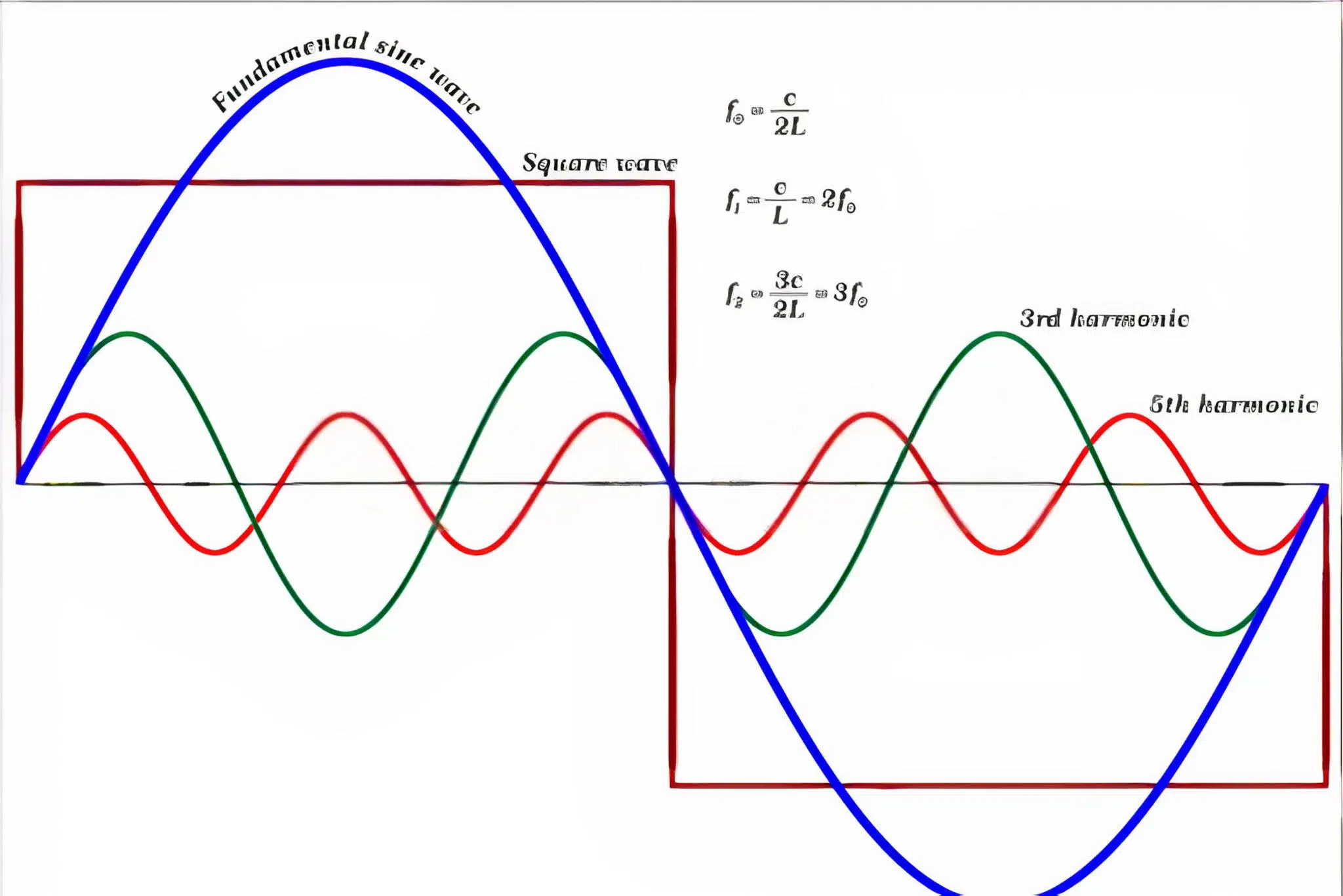
Harmonic Analysis are generated by nonlinear components in the electrical system which can distort the sine wave. Electrical components like variable frequency drives, uninterruptible power supplies, and inverters introduce harmonics of different orders into the electrical system.
Harmonics can have short-term as well as long-term consequences.it can cause a rise in temperature in the electrical network and the equipment, resulting in losses and shorter service life.
Care Labs is an authorized provider of electrical testing, inspection, calibration, and certification and can offer harmonic study and analysis services. Trained professionals will examine the systems for harmonic distortions, training programs, documentation, and PPE to ensure your electrical safety program is up to date, compliant, and comprehensive.
Effects of Harmonics:
-
- Loss of capacity on the power distribution line
- Overloaded transformer
- Overloaded conductor
- Reduction in performance in generation, transport, and energy usage system
- Aging of grid insulation components leading to energy reduction
- Voltage drops
- Derating of transformers
- Magnetic losses on electrical machine
- The possibility of amplification of the harmonics due to serial and parallel resonance
- Malfunctioning of an electrical system or its components
For managing and mitigating hazards associated with the problems listed above, harmonic analysis strategies are important for both solving the existing problems and preventing potential problems in the future.
Generation of Harmonics:
Harmonics are produced by nonlinear loads that absorb non-sinusoidal current. The most common loads include
-
- Frequency/variable speed drives
- Discharge lamps
- Rectifiers
- AC/DC converters
- Arc welding
- Induction ovens
- Computers and laptops
Methodology of harmonic study and analysis:
1.Design phase
-
- Model harmonic sources from nonlinear loads and powered electronic devices, simulate their impacts, and assess harmonic voltage and current distortion levels
- Calculation of harmonic distortion indices for both voltage and current
- Comparison of distortion levels and harmonic indices with standard code
- Identification of system parallel or series resonance frequencies
- To check the Presence of harmonic source frequencies near system parallel resonance points
- Installation of harmonic filters to reduce harmonic filters
- Using of transformer phase shift to eliminate harmonics and obtain overall reduction in harmonic distortion reduction
- The final system is then simulated to find out an overall harmonic voltage and current distortions
- Assess the overvoltage near the system parallel resonance points
- Assess the overcurrent near the system parallel resonance points
2.Operation Phase
3.Expansion Phase
Analyzing Harmonic Problems:
To analyze the harmonics a network analyzer can be used which can measure all the magnitudes of the installation. The commonly used portable analyzers are AR5L, QNA-P
Symptoms of Harmonics:
- On the Conductor:
-
- Cable heating
- Tripping of protection
- On the Neutral Conductor:
-
- Heating
- Degradation of conductor
- Tripping of protection
- Capacitor:
-
- Capacitor aging
- Destruction of capacitor
- Capacitor heating
- Transformers:
-
- Overheating of the winding
- Extra-large transformer
- Decrease in performance
- Motors:
-
- Overheating of the winding
- Winding degradation
- Decrease in performance
- Eccentricity on the axis
- Vibrations on the shaft
- Power Supply Unit:
-
- Difficulty in synchronization and switching of the unit
- Control and Measuring Equipment:
-
- Incorrect magnitude value
- Interferences in sensitive equipment
Filtering Strategies:
- Main Switch Board:
-
- Reduce the THD level generated towards the grid
- Decrease the declassification of the transformer
- Secondary Circuit Board:
-
- Reduce the effective value of current in the installation lines without power loss
- Loss of reduction
- Distortion current flow towards other equipment
- Slight attenuation of THD
- Individual Filtering:
-
- Reduce the distorting and effective current
- Loss reduction on the entire system
- Distortion current flow towards other equipment
- Slight attenuation of THD
The existence of harmonic distortion in the system becomes greater the larger the disturbance loads we use. The problems caused by the harmonics are well defined, and cannot be justified for an incident on the installation due to their presence.
The effects can be shown immediately (switch failure, incorrect operations in static equipment, etc.) or in the long term (capacitor battery resonance, transformer overheating, conductors and motors, measurement errors from measurement instruments, thermal losses, etc.).
By surpassing the maximum conductor isolation temperature by only 10ºC motors and transformers reduce their working life practically by half. Thus, it is strictly recommended to follow the procedure for the study of the analysis of harmonic disturbance.
Care Labs have our crew members deployed in various locations, so our specialists are nearby in case of a routine or emergency. In a very short period, Care Labs have been established as an ISO 9001:2008 certified organization and have acquired a reputed client base with excellent feedbacks.

Safe and Sustainable Hydropower in Canada
Hydropower in Canada- Past, present, and future! Imagine a world where 60% of the power demands are met by renewable energy sources. Wonder not, because it is a reality in Canada where hydropower is the star. Over a century ago, Canada took its first strides toward becoming a global leader in sustainable hydropower. As time […]

Cost Effective Arc Flash Study in Canada
The importance of arc flash studies in Canada’s robust manufacturing and energy sectors cannot be overstated. Why? Because it evaluates the risks associated with any electrical system. It is a core element to ensure the safety of personnel and equipment in a facility. Traditionally, it involves significant manpower, time, and resources. Enter Carelabs, a pioneer […]

The Role of Short Circuit Analysis in Enhancing Workplace Electrical Safety
Introduction Canada has one of the world’s most robust workplace electrical safety regulations. The Occupational Health and Safety (OHS) summarizes employers’ and supervisors’ rights and duties. Short circuit analysis identifies potential fault sections and their consequences in complex electrical systems. This helps develop a proper protection strategy and thus contributes to workplace electrical safety. Let […]

