What is Electric Motor Testing and Why is it Done | Carelabz.com

Electrical maintenance programs are designed to increase equipment promptness and uptime while decreasing capital operating cost. Electric Motor Testing is usually the first thing to be sacrificed when cutting back on operational expenses. But smart companies, understands that without proper maintenance programs, there is billions of dollars of lost revenue through increased motor repair costs, downtime, and waste in industrial and commercial companies.
Why is Electric Motor Testing Done?
After bearing failure, electrical faults are the most common mode of motor failure, so in addition, a properly planned electrical testing scheme is important for making sure of the plant reliability. The Electric Power Research Institute (EPRI) conducted a survey which brought into the light that, 48% of motor failures are because of electrical failures. The 48% can be again divided into rotor problems (12%) and winding problems (36%). The other 52% of failures are mechanical faults.
Many diagnostic tools, such as clamp-on ammeters, temperature sensors, a Megger or oscilloscope, can help illuminate these issues.
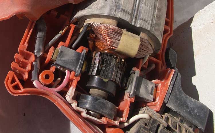
Winding defects occurs due to contamination, ageing of insulation, thermal overload, power surges, damaged wire/materials, and other causes. They start as energy crossing an insulation fault like moisture, which sets apart at least one turn. This creates extra stress and increase in temperature across the fault, which increases until the winding fails.
Some of the winding faults are:
- Between turns in a coil
- Between coils in a phase
- Between coils in different phases
- Between a coil or phase and ground
Fault finding of at least one of the above can save your facility countless hours of shut down and numerous dollars in savings.
What is Done During Electric Motor Testing?
There are various kinds of testing done on motor. They are:
Electric Motor Impulse TestingElectric Motor impulse testing is an integral part of predictive maintenance of electrical motors. Below are few questions that helps in explaining the influence of extensive impulse testing on a motor.
- Can impulse testing damage healthy or deteriorated insulation?
- Can DC Resistance, Inductance, Megger or HiPot tests diagnose weak turn-to-turn insulation?
- After failing an impulse test, are motor with weak insulation able to operate?
- Are motors with a turn-turn short able to perform continued function?
This was accomplished by putting a low voltage motor through extensive testing rigors, until inducing a failure. Following the failure, additional testing investigated the possible deteriorating effects on turn-turn insulation due to impulse testing beyond the motor’s dielectric breakdown. NOTE: This paper was edited from the original version of the IEEE paper published in 2003.
Electric Motor Rotation TestingCheck for fan or pump motor rotation when testing offline with the MCE. Fans may continue to slowly rotate due to drafting in the Plenum. Pumps that are attached to a shared header might remain rotating if other pumps attached to the header are functioning. This will adversely affect the Standard Test results, possibly creating higher than normal resistive and inductive imbalances.
Wound Rotor Electric Motor TestingWound rotor motors have a three-phase winding wound on the rotor which is connected to three phases of start-up resistors to provide current and speed control on start-up. Failed components in the resistor bank are common and often overlooked when troubleshooting. These damages can have major influence on the complete functioning of the motor and must be provided significant attention when troubleshooting these motors.
Electric Motor Insulation Resistance TestingElectric motor insulation exhibits a negative temperature coefficient, meaning as temperature increases, resistance decreases. This will make you certain that insulation resistance of a de-energized motor will reduce after commencing the motor. However, most often the resistance will initially increase after running due to moisture being evaporated by the increasing temperature of the windings. The standard IEEE43 on insulation resistance testing needs a temperature rectification to forty degrees Celsius, which could instantly turn suitable measured resistance readings into disappointingly low rectified resistance readings. Before sending a motor to be renovated, consider space heaters.
Meg-ohm TestThe meg-ohm test has long been the tool of choice for most engineers, and this simple test is often the only electrical test performed on a motor. However, while the meg-ohm test has a valid role to play, it is simply not capable of detecting all the likely faults within a motor’s winding.
PC tests Modern test equipment utilises PC control to provide automatic testing and fault diagnosis, thus removing the responsibility on the operator to interpret the results. The equipment can detect micro arcs, and to stop the test automatically. Database software permits resources to be saved with all test outputs, so that a practise can be built up with time, preferably from the inauguration of first-hand motor. Automated testing also helps remove operator error, inconsistency created by different operators applying different parameters and the possibility of the operator applying over-voltage to the motor. The latest testers combine all static electrical tests within one portable device, which also can create professional test reports.
Static or Insulation TestingIt is performed with the motor disconnected from the power supply. It is particularly done from the motor control cabinet and must be performed in a predetermined test sequence.
Winding Resistance TestIt will highlight dead shorts, loose connections and open circuits. Such tests must be performed with accurate equipment, which can measure down to 0.001 ohm. It is extremely important to correct the resistance values to a constant temperature, typically 20 degrees Celsius. The motor temperature should be quantified as precisely as achievable, and the copper temperature should be utilised wherever possible. A motor that has been recently operating is very unlikely to be at ambient temperature, so the use of ambient temperatures should be avoided. Upon conclusion of the test, the one imbalance between the phase-to-phase readings are quantified.
DC Step Voltage TestIt is typically performed at twice line voltage plus 1000 volts. The voltage is increased in a series of steps, and the leakage current is plotted. Effective insulation to earth will denote a linear plot, whereas a non-linear plot will indicate an insulation deterioration at that voltage where the leakage current instantly amplified. The step voltage test provides a great deal more information than the basic DC hipot test.
DC Hipot TestSimply applies a voltage, measures leakage current and calculates meg-ohms. If the meg-ohms are greater than the acknowledged smallest estimate, the motor passes. Even if there is an area of damaged insulation which causes a lower reading of meg-ohms, if that value is higher than the minimum accepted value, it will still pass.
Surge TestThis test is used to verify the turn-to-turn, coil-to-coil and phase-to- phase insulation condition and is typically performed at twice line voltage plus 1000 volts. It can identify dead shorts, frail insulation, unbalances and loose connections caused by incorrect winding. It works by injecting high voltage pulses into each phase, creating a potential difference between one turn and the next. The resulting sine waves from every phase must equal 1 another.
The above-mentioned tests are offline tests.Dynamic Motor Testing or online Testing** A more recent addition to electrical testing technologies, this involves measuring the voltage and current of the motor’s three phases, while the motor is functioning in its usual setting, and quantifying a host of data related to, the motor, the power supply and the load. Both electrical and mechanical issues can be identified.
Power quality values, including voltage level, unbalance and distortion are determined and compared to industry standards. Bad power quality can point to rise in temperature within motors, and as heat is the greatest enemy of insulation power quality problems must be determined and rectified where possible.
The Recommended Off-line in-Service Electric Motor Tests are
- Stator winding resistive imbalance
- Stator winding insulation resistance (Meg-Ohm checks)
- Polarization Index (PI)
- Step Voltage test
- Surge test
The Recommended Spare Electric Motor Tests are
- Stator winding resistive imbalance
- Stator winding insulation resistance (Meg-Ohm checks)
- Polarization Index (PI)
- Step Voltage test
- Surge test
The Recommended New/Refurbished Electric Motor Tests are
- Stator winding resistive imbalance
- Stator winding insulation resistance (Meg-Ohm checks)
- Polarization Index (PI)
- Step Voltage test
- Surge test
How is Motor Testing Done?
Three Phase
- Make sure the link for power supply is in decent state. Verify the connection bar for terminal (U, V, W). Connection type – STAR OR DELTA.
- Confirm the power supply VOLTAGE for electric motor. 230/400.
- With the help of multimeter, verify the continuity of winding from phase-to-phase (U to V, V to W, W to U). Every phase-to-phase should have a steadiness if winding is OK.
- Verify the motor winding reading in ohms utilising ohmmeter or multimeter for phase-to-phase terminal (U to V, V to W, W to U). The ohms reading for each winding must be the same (or nearly the same).
- Insulation resistance of motor winding using Insulation tester meter set to the 500 Volt scale (1000v DC)
- Verify from phase-to-phase (U to V, V to W, W to U) and
- Check from phase to earthing (U to E, V to E, W to E). Minimum test value of the electric motor is 1 Meg Ohm (1 MΩ).
- With the motor running, check the running amps of the motor using Clamp on meter.
- Match up to the full load current on the name plate of motor.
- After the completion of every step choose the condition of electrical motor either NEED TO REPAIRE or OK
Single Phase
- Utilising ohmmeter or multimeter, verify the motor winding readings in ohms. (C to S, C to R, S to R). The reading for start to run should be equal to C to S + C to R.
- Correct electrical terminal identification: There are three terminal connections on a hermetically sealed motor compressor and are as follows:
- Common (C)
- Start (S)
- Run (R)
- To determine the proper terminal, link these processes applies:
- The highest resistance reading is between the start and run terminals
- The middle resistance reading is between the start and common terminals.
- The lowest resistance reading is between the run and common terminals.
- Utilising Insulation tester meter set to the 500 Volt scale insulation resistance of motor winding can be found. Check from windings to earth (C to E, S to E, R to E). Minimum test value of the electric motor is 1 Meg Ohm (1 MΩ).
- Keeping the motor running, verify the running amps of the motor utilising a Clamp on meter.
- Compare to the FLA on the name plate of motor.
- If every step is completed – decide the condition of the electrical motor: OK or NEED TO REPAIR.
All Types
- Check the appearance of the motor. Verify for body deterioration or damage to the cooling fan blade or shaft.
- Manually rotate the shaft to check the bearing condition. Check for free & smooth rotation.
- Note the motor data from the motor NAME PLATE.
- Earth Continuity: Use your ohmmeter to verify the resistance between earth and motor frame is less than 0.5 Ω.
- Power supply, 415 v between Ll to L2, L3 to L1 and L2 to L3.
Benefits of Motor Testing
- Increase up-time
- Save money
- Conserve energy
- Improve safety
Get Started
Need expert support?
Carelabs delivers arc flash studies, power system analysis, and DEWA compliance services across the UAE.