Learn What is the Purpose of Lightning Arrester & Why is Testing Necessary
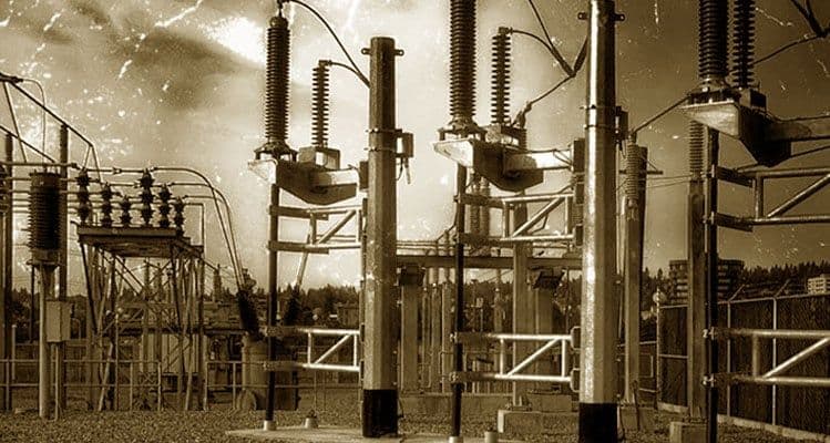
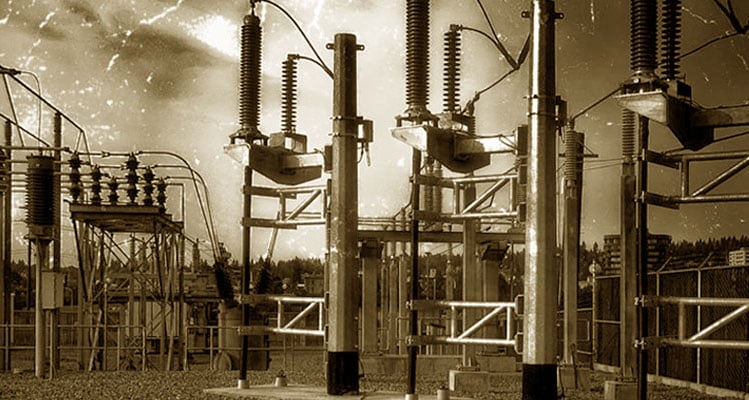
A Lightning Arrester, Surge arrester or Line arrester is a device used on electrical power systems and telecommunications systems to protect the insulation and conductors of the system from the damaging effects of lightning. The typical Lightning Arrester has a high-voltage terminal and a ground terminal. When a lightning surge (or switching surge) travels along the power line to the Arrester, the current from the surge is diverted through the Arrestor, in most cases to the earth.
Without good earth connections, even the most sophisticated of building lightning protection installations will be ineffective. However, the only way to ensure that the earth connections really are good is to test them. If protection fails or is absent, lightning that strikes the electrical system introduces thousands of kilo Volts that may damage the transmission lines, and can also cause severe damage to transformers and other electrical or electronic devices.
What is a Lightning Arrester/Surge Arrester?
Surge arresters are devices that help prevent damage to apparatus due to high voltages. The arrester provides a low-impedance path to ground for the current from a lightning strike or transient voltage and then restores to a normal operating conditions. A surge arrester may be compared to a relief valve on a boiler or hot water heater. It will release high pressure until a normal operating condition is reached. When the pressure is returned to normal, the safety valve is ready for the next operation. When a high voltage (greater than the normal line voltage) exists on the line, the arrester immediately furnishes a path to ground and thus limits and drains off the excess voltage. The arrester must provide this relief and then prevent any further flow of current to ground. The arrester has two functions, it must provide a point in the circuit at which an over-voltage pulse can pass to ground and second, to prevent any follow-up current from flowing to ground.
Various types of surge voltages can occur in electrical and electronic systems. They differ mainly with respect to their duration and amplitude. Depending on the cause, a surge voltage can last a few hundred microseconds, hours or even days. The amplitude can range from a few millivolts to some ten thousand volts. Lightning strikes are a special cause of surge voltages. Direct and indirect strikes can result not only in high surge voltage amplitudes, but also particularly high and sometimes long current flows, which then have very serious effects
Types of Lightning Arrester
- Rod gap arrester
- Sphere gap arrester
- Horn gap arrester
- Multi gap arrester
- Electrolyte type arrester
- Metal-oxide lightning arrester
Maintenance of LightningArrester
- Cleaning the outside of the arrester housing.
- The line should be de-energized before handling the arrester.
- The earth connection should be checked periodically.
- To record the readings of the surge counter.
- The line lead is securely fastened to the line conductor and arrester.
- The ground lead is securely fastened to the arrester terminal and ground.
Why Lightning Arrester Testing is Done?If protection fails or is absent, lightning that strikes the electrical system introduces 1000 of kilo Volts that may damage the transmission lines, and can also cause severe damage to transformers and other electrical or electronic devices. Lightning-produced extreme voltage spikes in incoming power lines can also damage electrical home appliances that’s why it is damn crucial to check the integrity of Lightning Arrester.
A direct lightning strike in the building can cause following damages:
- Impact on health or loss of life.
- Loss of technical services for the public.
- Loss of irreplaceable objects of cultural significance.
- Financial losses.
Lightning arrester testing should be scheduled as follows:
- Explosion-protected, physical structures should undergo a visual check every 6 months.
- The electrical test of the installations should be carried out once a year. •
- For systems with strict requirements in terms of safety technology, for example, the legislator can prescribe a comprehensive check. This can be necessary if there has been a lightning strike within a certain radius of the respective system.
Comprehensive testing in critical situations relates to physical structures that contain sensitive systems or systems with a large number of persons.
Lightning protective devices are developed, tested, and classified according to their own international series of product standards and they have defined protection functions and performance parameters to make them suitable for use in corresponding protection concepts.
Thus to achieve high system availability, system operators must regularly inspect and maintain their electrical system. This is stipulated by legislators, supervisory authorities or professional associations based on the respective system type. Regular testing and maintenance of lightning protection systems (external and internal lightning protection) is also required according to lightning protection standard IEC 62305-3.
Specialist knowledge is required in order to carry out professional testing of lightning protection systems. For this reason, this test must be carried out by a lightning protection expert, like Carelabs.
Inspecting the SPDs (Surge Protective Devices) is also part of this. The standard also demands that maintenance is properly documented.
New Developments in Lightning Arrester Testing Field
New developments, presently achieved for distribution range, foresee the replacement of the conventional porcelain housing with a polymeric one, allowing to improve the mechanical characteristics and the failure mode behaviour. Furthermore special applications for surge arresters, such as protection of gas insulated substations and prevention of lightning faults in transmissions lines, are now taken into consideration by several utilities. The evolution of surge arrester construction technologies and application requires a continuous revision of relevant standards and testing techniques. CESI has been actively involved in testing surge arresters since the 1960s, through the development and setting up of testing facilities and the participation to the major technical and standardization bodies. The paper analyses the most important aspects relevant to surge arrester testing, based on the most recent experience developed in CESI. Particular attention is focused on the short circuit test techniques to address the failure mode and on the ageing test procedures to investigate the long term performance of surge arresters.
What is Done During Lightning Arrester Testing?
Protective measures against lightning strike events are stipulated in lightning protection standard IEC 62305. Other standards in the series are IEC 61643-11, BS6651, IEC 61643-21 and IEC 61643-31. Over twelve years, the protection system will test under all seasonal conditions – these can significantly affect performance due to changes in resistance and other characteristics. Following tests can be conducted:
- Resistance testing
- Continuity testing
- Ground or soil resistivity testing
- Visual inspection
How do We Conduct Lightning Arrester Testing?Various tests carried out for surge arrestor testing are following:
Visual Inspection of Lightning Arrester
Visual inspection an installation should take into account the following key points and observations recorded in the detailed inspection report:
- Inspections should repeat at fixed intervals, not exceeding 12 months. If the intervals fixed at 11 months, the system will inspect throughout every season of the year over 11 years.
- The mechanical condition of all conductors, bonds, joints and earth electrodes should check and any observations noted.
- If a part is unable to inspect, this should note.
- The bonding of any recently installed/added services should check.
Thermal Image Testing (Infrared Testing) of lightning Arrester
The reason thermal imaging can assess the health of a surge arrester is because these components dissipate very little energy during steady state operation and seldom exhibit a temperatures much above ambient. Even the largest MOV arresters, e.g. 4 to 5 meters in height, dissipate less than 50 watts. With an arrester of that length, this does not create a visible temperature rise and makes any effort to measure temperature gradient above ambient a challenge.
The benefits of thermal imaging are significant:
- Speed of data collection. Indeed, there is no faster way at present to tell if an arrester is near end-of-life than a scan of its temperature.
- Accuracy from a distance is also excellent, especially if using a long-range camera lens.
The risk that an arrester is in the process of failing without also generating some heat is very low. At the same time, if an arrester is damaged by lightning strike or switching surge only days after its last thermal scan, it may well fail before the next scheduled scan. This potential for failure between successive scans is perhaps the only major negative of thermal imaging.
Power Factor Testing of Lightning Arrestor
Power factor testing is extremely sensitive to weather conditions. Tests is conducted in favourable conditions whenever possible. Measurements on surge arresters are always performed at the same or recommended test voltage since nonlinear elements may be built into an arrester.
Except for the specific purpose of investigation surface leakage, the exposed insulation surface of an arrester is kept clean and dry to prevent leakage from influencing the measurements. Extreme care is taken when handling arresters suspected of being damaged, since dangerously high gas pressures can build up within a sealed unit. The test mode and the number of tests performed will depend on the number of arresters in the stack. After performing tests, the test results are recorded on a test form.
For all power factor testing, the more information recorded at the time of testing will ensure the best comparison of results at the next routine test. Test data should be compared to factory or nameplate data if available. If no data is available, compare the test results to prior tests on the same arrester and results of similar tests on similar arresters. The following additional information should be recorded on the test form.
- Record all the nameplate information of the arrester.
- Identify each set of readings with the arrester serial number.
- Note any special or unusual test connections or conditions.
- Record actual test voltage, current, watts, power factor and capacitance. Correct the current and watts to a standard test voltage 2.5kV or 10kV.
- Surge arresters are often rated on the basis of watts loss. To obtain the equivalent 10 kV watts loss from a measurement of capacitance and power factor, perform the following calculations if the test set does not display the results.
Watts loss = CpF x %DF x 377 x 10-6 (for 60 Hz)**Watts loss = CpF x %DF x 314 x 10-6 (for 50 Hz)**Where: CpF = capacitance in picofarads %DF = percent dissipation (power factor) ß Record ambient temperature and relative humidity and a general indication of weather conditions at the time of the test.
Fall of Potential Testing Method of Lightning Arrester
Fall of Potential method involves the electrode under test; two reference electrodes, a set of leads and four-pole test meter.
This method, however, is only practical if the electrode to test is located near to virgin ground where test electrodes can drive. In reality, in town and city centres, this is very often not the case. Presence of buried services and pipes may also influence the test current and the last test value may be corrupted as a result of these external influences. Reference electrodes is set away from such potential disturbances. Where practical conditions dictate that the ‘Fall of Potential’ method cannot be used, the ‘Dead/Known Earth’ method is really the only practical alternative.
Dead Earth Testing Method of Lighting Arrester
The ‘dead earth’ could be any low-resistance earth not directly or unexpectedly connected to the earth under test. A connection made from a suitable earth to the test meter, which is in turn connected to the electrode under test will show the lightning protection system acting as the known ‘dead/known’ earth.
A reading is then taken and the ohmic value achieved is effectively the series resistance of the electrode under test and the dead earth.
Leakage Electricity of Lightning Arrester
The Leakage Electricity Monitors are used to measure the Leakage Current of Surge Arrester, and in case of high leakage current Surge Arrester is replaced.
The power loss can be checked by several methods given below:
- Using a voltage signal as reference.
- Compensating the capacitive element by using a voltage signal.
- Capacitive compensation by combining the leakage current of the three phases.
- Third order harmonic analysis.
- Direct determination of the power losses.
- Third order harmonic analysis with compensation for harmonics in the voltage.
Other usual testscarried out on Lightning arrestors are harmonic tests, hipot test and insulation resistance test
Benefits of Lightning Arrester Testing
- Lightning protection testing would make sure that all structures, key electrical and electronic installations are safe from the effect of lightning strike.
- The financial benefits are determined as follows: how does the total annual cost for a lightning protection system compare to the costs of potential damage without a protection system? The cost evaluation is based on the expenditures for the planning, assembly, and maintenance of the lightning protection system.
Statistics show the UK alone subjected to around two million strikes per year and, to make sure your lightning protection system is functional when called upon, bearing in mind you have no way of determining when that any maintenance work should be carried out with suitable expediency.
In the hands of experienced engineers, proper testing and maintenance of lightning protection systems can become a routine, but very necessary, part of a comprehensive safety programme. At the very least the consequences of not taking a thorough approach could incur unnecessary costs but, given the destructive potential of a lightning strike, those consequences could be much worse.
All lightning protection systems and static earthen systems must inspect and test by skilled person using calibrated test equipment. Complete lightning protection testing would make sure that all structures, key electrical and electronic installations are safe from the effect of lightning strike.
Get Started
Need expert support?
Carelabs delivers arc flash studies, power system analysis, and DEWA compliance services across the UAE.