LOAD FLOW STUDY AND ANALYSIS
Load Flow Analysis or Power Flow Analysis is the most crucial tactic to exploring problems in power system operating and planning. Based on a specified generating state and transmission network structure, load flow analysis solves the steady operation state with node voltages and branch power flow in the power system. Load flow provides sinusoidal steady state of complete system – real and reactive power generated, voltages and absorbed and line losses. Since the load is a static quantity and it is the power that flows through transmission lines it is also known as Power Flow studies.
Why Load Flow Analysis is Important?
Performing a power flow study helps you plan ahead and account for various hypothetical situations. For example, if a transmission line is to be taken off line for maintenance, can the remaining lines in the system handle the required loads without exceeding their rated values.
Power flow studies are undertaken for various reasons, some of which are the following:
- The line flows
- The bus voltages and system voltage profile
- The effect of change in configuration and incorporating new circuits on system loading
- The effect of temporary loss of transmission capacity and (or) generation on system loading and accompanied effects.
- The effect of in-phase and quadrative boost voltages on system loading
- Economic system operation
- System loss minimization
- Transformer tap setting for economic operation
- Possible improvements to an existing system by change of conductor sizes and system voltages
Through the load flow studies we can attain the voltage levels and angles at every bus in steady state. This is rather important as the magnitudes of the bus voltages are required to be held within a specified limit. Once the bus voltage angles and levels are calculated using the load flow, reactive and real power drift through every line can be calculated. Also based on the difference between power flow in the sending and receiving ends, the losses in a particular line can also be computed. Moreover, from the line flow we can also find out the over and under load states. Power flow or load flow solution is essential for continuous evaluation of the performance of the power systems so that suitable control measures can be taken in case of necessity.
What is done During Load Flow Analysis?
A load flow study is the analysis of an electrical network carried out by an electrical engineer. The purpose is to understand how power flows around the electrical network. Implementation of a load flow study helps the engineer in designing electrical systems which functions correctly, have enough power supplied by the power grid, where gear is properly sized, reactive power compensation is properly placed and transformer taps are optimised.
Understanding how power flows is crucial to the design of any system. For simple radial systems, often no formal load flow study is performed, but unchangeably it is part of any analysis performed during the design of the system. For larger power distribution systems, a formal load flow study is carried out; typically using software, with the results presented in a report.
While performing a load flow study, it is important to mathematically describe the electrical network and perform calculations to get the necessary results.
The study of load flow involves the following three steps:
- Modelling of power system components and network.
- Development of load flow equations.
- Solving the load flow equations using numerical techniques.
How is Load Flow Study Performed?
Mathematical Analysis
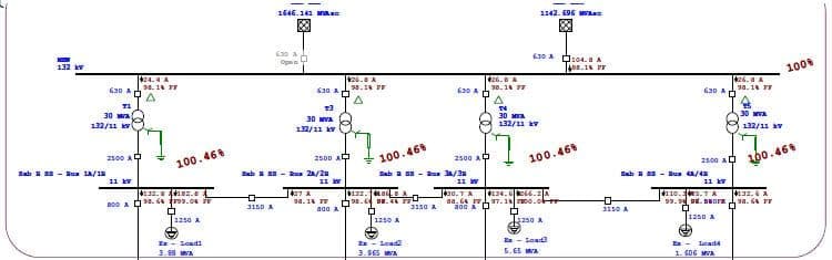
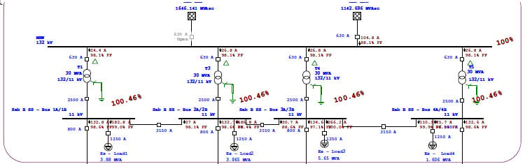
There are number of steps to be done while mathematically analysing load flow. They are:Step 1: Represent the system by its one line diagram.
Step 2: Convert all quantities to Per Unit. We need to find all the parameters that we are given with respect to one common base value. This base value is normally clearly mentioned, but if not we can presume one and move on.
Step 3: Draw the Impedance Diagram.
Step 4: Obtain the Ybus matrix.
Step 5: Classify the buses
Step 6: Start answering the missing variables, by assumptions (unless it is specified otherwise).
Step 7: Find approximations for the Real and Reactive Power that we are given, using the assumed and given values for voltage/angles/admittance.
Step 8: Write the Jacobian Matrix for the first iteration of the Newton Raphson Method.
Step 9: Solve for the unknown differences, using Cramers Rule.
Step 10: We now need to repeat step 7 – 9 iteratively until we obtain an accurate value for the unknown differences as the [Symbol]0. Normally we only do 2 iterations. And other indefinite parameters are calculated.
Software Analysis
Software is utilised in most of the realistic or real-time conditions since they are easier. In doing this, the electrical engineer builds a network of nodes interconnected by admittances (impedances).
Each system node has four key parameters:
- Active power (P)
- Reactive power (Q )
- Voltage magnitude (V)
- Voltage phase angle (δ)
In defining nodes in a software model, the engineer typically considers three types:
- Load Bus [P-Q bus], a bus where the real and reactive power are specified.
- Generator Bus [P-V bus], a bus in which the voltage and real power generation is known.
- Slack Bus (Swing bus), where the voltage magnitude and phase are assumed known.
In a study most, nodes are of the load bus type. The generator bus type is all the nodes that have a generator connected. While more than one slack bus could be defined, it is usual to have only one, and this is chosen as the connection point to the main grid supply.
The engineer will construct the network mock-up by setting busbars, grid connections, interconnections, generators and major items of equipment. The software will then carry out the necessary calculations.
Using software simplifies the carrying out of a load flow study. However, the selection of input data required, level of detail to model, verification and interpretation of the output and utilising this to achieve the required design still requires the input of a skilled electrical engineer.
Carelabs is authorized provider of Electrical Installation’s Study, Analysis, Inspection, and Certification services in UAE, and offer load flow study and analysis services.
Get Started
Need expert support?
Carelabs delivers arc flash studies, power system analysis, and DEWA compliance services across the UAE.