Learn About Continuity Testing and How to do it | Carelabz.com

A continuity test verifies that current will flow in an electrical circuit (i.e. that the circuit is continuous). The test is performed by placing a small voltage between 2 or more endpoints of the circuit. The flow of current can be verified qualitatively, by observing a light or buzzer in series with the circuit actuates or quantitatively, using a multimeter to measure the resistance between the endpoint.
In continuity testing the resistance between two points is measured. Low resistance means that the circuit is closed and there is electrical continuity. High resistance means that the circuit is open and continuity is lacking. Continuity testing can also help determine if two points are connected that should not be.
Why Continuity Testing is Done?
Regulation 610.1 of BS 7671:2008 IEE Wiring Regulations Seventeenth Edition requires that every installation shall, during erection and on completion before being put into service, be inspected and tested to verify that the requirements of the Regulations have been met. The purpose of this test is to verify that the CPC forms a continuous path around the circuit under test.
A continuity test is an important test in determining the damaged components or broken conductors in a circuit. It can also help in determining if the soldering is good, if the resistance is too high for flow of current or if the electrical wire is broken between two points. A continuity test can also help in verifying or reverse-engineering an electrical circuit or connection.
Continuity testing can be used to detect cold solder connections and problems with wire and cable products. In field applications, handheld multimeters with dual probes are used. In addition, this form of electrical testing can be used to check connections between the pads and traces on printed circuit boards (PCBs).
What is Done During Continuity Testing?
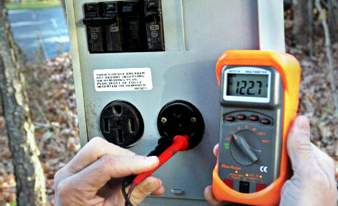
The most common and basic way of performing a continuity test is with the help of a resistance tester (any simple Multimeter with this function will do). This is because the resistance of conductors between the two ends is usually very small (less than 100 ohm).
Continuity tester has two leads connected to a small battery, and when you touch the leads together to complete the circuit, the meter should register 0 resistance or if you have a dedicated continuity tester, the light should come on. If you’re using a digital multimeter, the device may also beep.
Continuity of protective conductors including main and supplementary equipotential bonding. Every protective conductor, including circuit protective conductors, the earthing conductor, main and supplementary bonding conductors should be tested to verify that all bonding conductors are connected to the supply earth. Tests are made between the main earthing terminal (this may be the earth bar in the consumer unit where there is no distribution board present) and the ends of each bonding conductor.
How to do Continuity Testing?Measuring Continuity in an Electrical Device:
This method is used for testing continuity is an easy and reliable way to determine whether a switch or outlet has internal damage. If you’re using a multimeter, set it to the “Continuity” function, or select a midrange resistance setting, in ohms.
Step 1:Turn Off the Breaker That Controls the Circuit
The power needs to be off when testing continuity. Verify that no electricity is flowing by using a noncontact circuit tester.
Step 2:Check the Tester
Check the tester by putting the leads together and ensuring that the device lights up, beeps or registers 0 ohms of resistance.
Step 3:Touch Lead to Terminal
Touch one lead on one of the hot terminals of the device, identified by a brass screw.
Step 4:Touch Other Lead to Terminal
Place the other lead on any other terminal except the green ground terminal. If the tester lights up, beeps or shows 0 resistance, it means that electricity can flow freely between those terminals, and in most cases, that means that the device is good. If the device is a switch, the tester should go off and on when you flip the switch.
You can use this technique to check appliance switches, thermostats and fuses. Be sure the power is off, then touch the leads to the terminals of the device in question.
Continuity of Circuit Protective Conductors (CPC)The test is carried out as follows:
- Temporarily link the line conductor to the CPC in the Consumer Unit.
- Test between the line and the CPC at each accessory point e.g. a ceiling rose, switch or socket outlet. The reading obtained at each accessory point should be a low resistance value. The resistance measured at the extremity of the circuit is the sum of the resistances of the line conductor and protective conductor (R1 + R2).
When we talk about Continuity Testing within the Inspection and Testing Procedure then we apply the same principle, but with a bit more detail.Step 1: Select the circuit to be tested in the distribution board and remove the Line conductor from the MCB
Step 2: Connect the Line conductor to the Earth conductor (for simplicity, connect it to one of the spare terminals on the Earth bar). This way you will form a circuit which is half made up of the Line conductor and half made of the Earth conductor (provided that the terminations within the electrical accessories such as wall sockets are correct).
Step 3: Select the correct test function on the test equipment, which is the low reading ohm meter function (Megger 1553).
Step 4:. Do not forget to null the test instrument if required (you can do this by connecting the two test leads together and pressing the TEST button until the measured value on the display becomes zero ohm`s)
Step 5: Measure between Line and Earth terminals at each outlet in the circuit. The highest reading should be recorded on the Schedule of Test Results as the value of (R1+R2).
Step 6:.Return the Line conductor back in to the MCB
Continuity Testing Overview
- Continuity is the presence of a complete path for current flow. A circuit is complete when its switch is closed.
- A digital multimeter’s Continuity Test mode can be used to test switches, fuses, electrical connections, conductors and other components. A good fuse, for example, should have continuity.
- A DMM emits an audible response (a beep) when it detects a complete path.
- The beep, an audible indicator, permits technicians to focus on testing procedures without looking at the multimeter display.
- When testing for continuity, a multimeter beeps based on the resistance of the component being tested. That resistance is determined by the range setting of the multimeter. Examples:
- If the range is set to 400.0 Ω, a multimeter typically beeps if the component has a resistance of 40 Ω or less.
- If the range is set 4.000 kΩ, a multimeter typically beeps if the component has a resistance of 200 Ω or less.
- The lowest range setting should be used when testing circuit components that should have low-resistance value such as electrical connections or switch contacts.
Important Things to Remember
- Do not forget that with the lighting circuits the intermediate switch should be switched to all available positions so that all the conductors could be tested for continuity.
- Do not forget to link out the dimmer switch on the other lighting circuit, otherwise you will get wrong test results.
- Remember, that by doing these steps you will also confirm the correct polarity of the conductors, so there is no need to do polarity dead tests again.
- Remember to constantly inspect the installation for faults and signs of damages.
Multimeters and ohmmeters are normally used for continuity tests. Specialized continuity testers are also available which are more basic in nature, inexpensive and have a light bulb which glows in the case of current flow. The continuity test is performed on an electrical circuit when it is not powered and with help of the testing device.
Can an electronic circuit which is passing currents be tested by a multi-meter’s continuity test? Would it be meaningful or harmful? Why?
A continuity test is like a simplified resistance/ohms measurement. A basic method is to apply a voltage across the resistor and measure the current OR apply a current and measure the voltage. Then through R = V/I you can calculate the resistance.
Imagine you applied 100 V DC but your meter can only handle 10 V when in the continuity test mode. Such a test is completely meaningless, and potentially damaging to the meter. If you want to test continuity or resistance, remove all sources of power, and discharge any stored energy sources.
The meter is sourcing a (usually low) test voltage. If you connect it to something that is already powered, you are connecting the two sources together, and the meter isn’t designed to handle external sources in continuity or resistance (or capacitance, or inductance, or any other passive) mode..
Risks of Introducing a Voltage Through the Multimeter Leads
- There is a risk of certain parts being damaged, especially parts that cannot tolerate the 1 to 9 volts that a multimeter might deliver across the probes in continuity mode.
- The above is especially true when the component (or other components on connected traces, which will also be affected) is not powered. Many parts can tolerate voltages when powered but not otherwise.
- To minimize the voltage, an option is to use the multimeter in resistance mode, at the lowest resistance setting – The higher resistance scales work on higher probe voltage, going by a quick check on a couple of multimeters at my desk.
- Note that basic multimeters often combine continuity and diode testing modes, so the voltage is at minimum sufficient to forward bias silicon diodes and perhaps LEDs. This means a voltage of 2 to 3 volts.
Benefits of Continuity Testing
- Return of that investment is a long-term one and it will also save time.
- Tests can be done 24/7.
- Fewer human resources are required.
- Reusability: The scripts are reusable. You don’t need new scripts all the time.
- Reliability: It is more reliable and quicker way when running boring repetitive standardized tests which cannot be skipped.
- It not only checks for continuity but also for shorts.
Get Started
Need expert support?
Carelabs delivers arc flash studies, power system analysis, and DEWA compliance services across the UAE.