Learn What is Polarity Test & Why to Conduct Polarity Test | Carelabz.com

Polarity in electrical terms refers to the positive or negative conductors within a dc circuit, or to the Line and Neutral conductor within an ac circuit. Electrical polarity (positive and negative) is the direction of current flow in an electrical circuit. Current flows from the positive pole (terminal) to the negative pole. Electrons flow from negative to positive. In a direct current (DC) circuit, current flows in one direction only, and one pole is always negative and the other pole is always positive. In an alternating current (AC) circuit the two poles alternate between negative and positive and the direction of the current (electron flow) reverses periodically.
Most multimeters, including digital multimeters, can do this. Regarding alternating current in the context of an ac supply, a polarity test is done to ensure that the line and neutral conductors are connected the correct way around at, for example, electrical sockets, Edison-screw lamp holders, etc.
In the context of electricity installations, a polarity test is used to confirm the correct connection of the line and neutral conductors. For example, for an Edison-screw lamp holder, it is important that the line conductor is connected to the centre terminal and the neutral conductor is connected to the outer conductor. Similarly, it’s important to confirm that switches are located in the line conductor not the neutral conductor.
Whydo aPolarity Test?
The purpose of a polarity test to ensure that all single pole devices (fuses, switches and circuit breakers) are connected in the phase conductor only. We cannot simply trust that the electricians have connected things up the right way; everyone makes mistakes, even if it’s your own work. Since ac installations consist of a Live and a Neutral conductor, it is extremely important that these conductors are connected the right way around, within all electrical accessories such as wall sockets or plugs. To ensure this, polarity test is done at each relevant point. This simple test is just as important as all the others, and many serious injuries and electrocutions could have been prevented if only polarity checks had been carried out.
There are 4 different scenarios that require a polarity test, these are:
- All single pole devices (fuses, switches and circuit breakers) are connected in the phase conductor only.
- The phase conductor must be connected to the centre terminal of an Edison screw lamp holder (with the exception of E14 & E27 lamp holders, these are European and occasionally crop up in the exam).
- All polarities of socket outlets (ring & radial) must be verified.
- The polarity of the mains supply must be correct, using an approved voltage tester. (This is done with the supply connected, therefore carried out at a different stage then the above three).
What is Polarity Testing?
A test that creates a circuit using the phase conductor and the single pole device in question, breaking the circuit when operating the device, means that the reading on the instrument will change, and thus confirming that that device must be connected in the phase conductor.
This test will verify that all the switches installed in the system are connected in current carrying conductor and not in neutral. For example, if you isolate or switch the neutral of a circuit via a single-pole circuit breaker or switch, it would appear that the circuit is dead where in fact it is still live.
If polarity is not correctly determined there may be a risk of electric shock during maintenance procedures.
There are 2 methods that can be adopted when conducting a polarity test. These are described below.
Method 1for Polarity Test
This method is exactly the same as test method one for ‘Continuity Of Protective Conductors’ if we take a lighting circuit, by putting a temporary link between phase and circuit protective conductors (cpc), at the consumers unit and our instrument at lamp holders themselves, we are creating a circuit. When we operate the light switch, the instrument changes, and then changes back to the original reading on operation of the switch again. If the reading did not change, then the switch is likely to be connected in the Neutral. (Not good!) With a little foresight this could be carried out at the same time as the continuity test. The only difference being, for radial circuits every point must be tested. The main benefit with this is it allows you to conduct 2 tests at the same time, polarity and R1 + R2.
Method 2 for Polarity Test
This method, like wise is similar to test 2 of the continuity test, we simply use a wander lead as the return lead. There is little use for this method, within the polarity test. Method 1 is less clumsy, and is far more flexible and useful.
A Note on radial socket outlets: We have covered ring final circuits, but radial final circuits involving sockets can prove to be little more involved. Why?
Well simply because doing a polarity check using method 1, will not uncover a phase to cpc reversal. If the phase and cpc were reversed at the socket, the instrument will still provide a reading. It will however tell you if you have a phase to neutral reversal (you wouldn’t have a reading at the socket). So what can we do to expose a phase? We can simply link the phase and neutral together at the board, and put our instrument across phase and neutral at the socket, if the cpc and phase have been reversed, then no reading will be recorded on the instrument.
How is Polarity Test Done?
We perform following steps for polarity testing
Step 1:Polarity by Visual Inspection
By using your knowledge and sight, correct termination of cables relating to core colours can be established. It is essential that polarity is checked visually during the process of installation, especially in cases where checking by testing is impractical.
Step2:Polarity by Continuity Testing
If visual inspection is not possible, you will need to use a low-resistance ohmmeter for this test. When you continuity test radial and ring final circuits, part of the process is to test and visually inspect the polarity of fixed equipment and socket outlets.
Steps:
- Switch off the circuit breaker supplying the circuit.
- From the specific circuit, put a temporary link that will connect the line conductor and the CPC or any equipotential bonding conductors. It will serve as a testing point for convenience.
- Conduct continuity testing by placing the test leads across the line conductor and the nearest CPC or any exposed conductive parts of the circuit.
- If the instrument shows zero reading (with continuity sound) then the switch is connected properly to the line conductor.
- If the instrument shows some significant ohmic value then the switch is not connected to the line conductor. Interchange the connections to fix the problem.
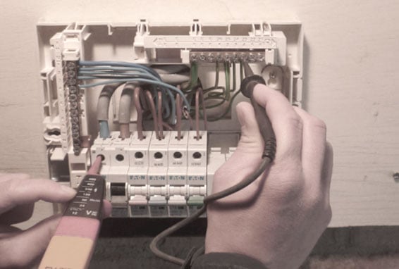
Step 3:Live Testing for Polarity
If the two methods are not possible due to urgency we can perform live polarity testing by using the approved voltage GS38.
Steps:
- Test between LINE and NEUTRAL terminals.
- Test between LINE and EARTH terminals.
- Test between NEUTRAL and EARTH terminals.
The test instrument should indicate full voltage (230V) between Line-Neutral and Line-Earth conductors. No voltage should be detected between Neutral-Earth.
The requirements for polarity test are:
- All fuses and single pole switches are in the phase conductor.
- The centre contact of equipment like lamp holder is connected to the phase conductor.
- All socket outlets and similar accessories are correctly wired.
Although polarity is towards the end of the recommended test sequence, it is sensible, on lighting circuits, for example, to conduct this test at the same time as that for continuity of CPCs. (When recording R1+R2). Polarity on ring final circuit conductors, is achieved simply by conducting the ring circuit test.
Reading across L&N should be
(r1+rn)/4 +/- 0.05 Ohms
And for across L&CPC
(r1+r2)/4 +/- 0.05 Ohms.
For radial socket outlet circuits, however, this is a little more difficult. The continuity of the CPC will have already been proved by linking phase and CPC and measuring between the same terminals at each socket. Whilst a phase-CPC reversal would not have shown, a phase-neutral reversal would, as there would have been no reading at the socket in question. This would have been remedied, and so only phase-CPC reversals need to be checked. This can be done by linking together phase and neutral at the origin and testing between the same terminals at each.
A phase-CPC reversal will result in no reading at the socket in question. When the supply is connected, it is important to check that the incoming supply is correct. This is done using an approved voltage indicator at the intake position or close to it.
TestingPolarity in Lightning Circuit and Transformer
Test of Polarity of Lighting Circuits
This test must be done with the supply disconnected and may be carried out as follows:
Remove circuit FUSE or open MCB. Remove all lamps from relevant circuit. Connect one end of the long trailing lead to the outgoing terminal of the circuit MCB. Using the other end in conjunction with the test meter leads, take readings from the phase terminal at all the points around the circuit e.g. switches and ES lamp holders. Continuity (approx. resistance of conductor involved) at each point ensures that polarity is correct.
If the supply is disconnected from the installation the long trailing lead may be connected to the phase busbar and the MCB should then be left in the “on” position.
Test of Polarity of Transformers
In situations where the secondary bushing identification is not available or when a transformer has been rewound, it may be necessary to determine the transformer polarity by test. The following procedure can be used.
The left-hand primary bushing and the left-hand secondary bushing are temporarily jumpered together and a test voltage is applied to the transformer primary. The resultant voltage is measured between the right-hand bushings. If the measured voltage is greater than the applied voltage, the transformer is Additive Polarity because the polarity is such that the secondary voltage is being added to the applied primary voltage. If, however, the measured voltage across the right-hand bushings is less than the applied primary voltage, the transformer is Subtractive Polarity.
Get Started
Need expert support?
Carelabs delivers arc flash studies, power system analysis, and DEWA compliance services across the UAE.