Developed early in the 20th century, the insulation resistance (IR) test is the oldest and most widely used test for assessing the quality of insulation. The Insulation Resistance Test is the second test required by the electrical safety testing standards. The Insulation Resistance Test consists in measuring the Insulation resistance of a device under test, while phase and neutral are short circuited together. The measured resistance has to be higher than the indicated limit from the international standards. A megohmmeter (also called insulation resistance tester, teraohmmeter) is used to measure the ohmic value of an insulator under a direct voltage of great stability.
Insulation cannot be perfect in the same way that something cannot be frictionless. This means that there will always be a little bit of current travelling through. This is known as “leakage current”. It’s acceptable with good insulation, but if the insulation deteriorates, leakage can start causing trouble. So what makes “good” insulation? Well, it needs a high resistance to current, and it needs to be able to sustain high resistance for a long time
Why Insulation Resistance Test is Done?
Insulation starts to age as soon as it’s made. As it ages, its insulating performance deteriorates. Any harsh installation environments, especially those with temperature extremes and/or chemical contamination, accelerates this process. Stresses due to different factors like:
- Electrical stresses: Mainly linked to overvoltage and undervoltage.
- Mechanical stresses: Frequent start-up and shutdown sequences can cause mechanical stresses.
- Balancing problems on rotating machinery and any direct stress to the cables and the installations in general.
- Chemical stresses: The proximity of chemicals, oils, corrosive vapours and dust, in general, affects the insulation performance of the materials.
- Stresses linked to temperature variations: When combined with the mechanical stresses caused by the start-up and shutdown sequences, expansion and contraction stresses affect the properties of the insulating materials. Operation at extreme temperatures also leads to aging of the materials.
- Environmental contamination causes aging acceleration of insulation.
This wear and tear can reduce the electrical resistivity of the insulating materials, thus increasing leakage currents that lead to incidents which may be serious in terms of both safety (people and property) and the costs of production stoppages. Thus it’s important to identify this deterioration quickly so that corrective steps can be taken. In addition to the measurements carried out on new and reconditioned equipment during commissioning, regular insulation testing on installations and equipment helps to avoid such incidents through preventive maintenance. These tests detect ageing and premature deterioration of the insulating properties before they reach a level likely to cause the incidents described above.
This test is often used as a customer acceptance test, with minimum insulation resistance per unit length often specified by the customer. The results obtained from IR Test are not intended to be useful in finding localized defects in the insulation as in a true HIPOT test, but rather give information on the quality of the bulk material used as the insulation.
Wire and cable manufacturers use the insulation resistance test to track their insulation manufacturing processes, and spot developing problems before process variables drift outside of allowed limit.
What is Done During Insulation Resistance Measurement?
The measurement of insulation resistance is a common routine test performed on all types of electrical wires and cables. Its objective is to measure the ohmmic value of the insulation under a direct voltage of great stability, generally 50, 100, 250, 500, or 1000 VDC. The ohmmic value of the insulation resistance is expressed in megohms (MΩ). To conform to specific standards, the insulation resistance test can be performed under voltages up to 1500VDC. Due to the stability of the voltage source, it is possible to adjust the test voltage by steps of 1 volt.
The stability of the voltage is critical; a non-regulated voltage will drop sharply in presence of a bad insulation which will cause an erroneous measurement.
After the required connections are made, you apply the test voltage for a period of one min. During this interval, the resistance should drop or remain relatively steady. Larger insulation systems will show a steady decrease, while smaller systems will remain steady because the capacitive and absorption currents drop to zero faster on smaller insulation systems. After one min, read and record the resistance value
Selection of IR Testers (Megger):
| Voltage Level | IR Tester |
| 650V | 500V DC |
| 1.1KV | 1KV DC |
| 3.3KV | 2.5KV DC |
| 66Kv and Above | 5KV DC |
How Insulation Resistance is Measured?
Insulation resistance measurement is done using an IR tester. This is a portable tool that is more or less an ohmmeter with a built in generator that’s used to produce a high DC voltage. The voltage usually measures at least 500V, and causes a current to flow around the surface of the insulation. This gives a reading of the IR in ohms.
Insulation resistance measurement is based on Ohm’s Law. (R=V/I). By injecting a known DC voltage lower than the voltage for dielectric testing and then measuring the current flowing, it is very simple to determine the value of the resistance. In principle, the value of the insulation resistance is very high but not infinite, so by measuring the low current flowing, the megohmmeter indicates the insulation resistance value, providing a result in kW, MW, GW and also TW (on some models). This resistance characterizes the quality of the insulation between two conductors and gives a good indication of the risks of leakage currents flowing.
Well, if you are looking at a high number of IR, you have some good insulation. If it is relatively low, on the other hand, the insulation is poor.
However, this is not everything – a variety of factors can affect the IR, including temperature and humidity. You will have to do a number of tests over time to make sure the IR value stays more or less the same. Value of insulation resistance is often expressed in gigaohms [GΩ].
Good Insulation is when megger reading increases first then remain constant. Bad Insulation is when megger reading increases first and then decreases.
Expected IR value gets on Temp. 20 to 30 decree centigrade. If this temperature reduces by 10 degree centigrade, IR values will increased by two times. If above temperature increased by 70 degree centigrade IR values decreases by 700 times.
In order to measure big electrical resistance, measurement voltage has to be far higher than it is in case of standard resistance measurements. This voltage is often within the range from 100 VDC to 1000 VDC and it cannot be used for measuring resistance of electronic components because they could be damaged.
High Value Resistance
To measure a high value resistance, techniques for measuring a low value current are used. A constant voltage source is applied to the resistance to be measured and the resulting current is read on a highly sensitive ammeter circuit that can display the resistance value.
Two types of ammeter circuits are used on our range of insulation resistance tester, each circuit being chosen depending on the resistance values to be measured.
Shunt Ammeter Circuit
The voltmeter input, associated to a resistance, forms the shunt ammeter circuit. This setting allows measuring any value of I, many combinations of sensitivity and values of RI. This circuit is used for current measurement of high values which correspond to resistance measurement of low values.
Feedback Ammeter Circuit
This circuit is the one mostly used on our instruments. It covers the resistance measurement of high values.
Indeed the value of a high resistance depends of the voltage applied to it. Other factors intervene in the high value resistance measurement. Temperature and relative humidity are two important parameters which influence the resistance value of an insulator.
Difference Between Dielectric Strength Test and IR Test
Dielectric strength testing, also called “breakdown testing”, measures an insulation’s ability to withstand a medium-duration voltage surge without sparkover occurring. In reality, this voltage surge may be due to lightning or the induction caused by a fault on a power transmission line. The main purpose of this test is to ensure that the construction rules concerning leakage paths and clearances have been followed. This test is often performed by applying an AC voltage but can also be done with a DC voltage. This type of measurement requires a hipot tester. The result obtained is a voltage value usually expressed in kilovolts (kV). Dielectric testing may be destructive in the event of a fault, depending on the test levels and the available energy in the instrument. For this reason, it is reserved for type tests on new or reconditioned equipment.
Insulation resistance measurement, however, is non-destructive under normal test conditions. Carried out by applying a DC voltage with a smaller amplitude than for dielectric testing, it yields a result expressed in kW, MW, GW or TW. This resistance indicates the quality of the insulation between two conductors. Because it is non-destructive, it is particularly useful for monitoring insulation aging during the operating life of electrical equipment or installations. This measurement is performed using an insulation tester, also called a megohmmeter
Factors affecting values of insulation resistance:
- Capacitance Charging Current: Current that starts out high and drops after the insulation has been charged to full voltage (much like water flow in a garden hose when you first turn on the spigot).
- Absorption Current: Also an initially high current which then drops (for reasons discussed under the section Time-Resistance Method).
- Conduction or Leakage Current A small essentially steady current both through and over the insulation.
Safety Requirements for Insulation Resistance Measurement
- All equipment under test must be disconnected and isolated.
- Equipment should be discharged (shunted or shorted out) for at least as long as the test voltage was applied in order to be absolutely safe for the person conducting the test.
- Never use Megger in an explosive atmosphere.
- Make sure all switches are blocked out and cable ends marked properly for safety.
- Make sure when testing for earth, that the far end of the conductor is not touching, otherwise the test will show faulty insulation when such is not actually the case.
- Make sure that all connections in the test circuit are tight.
- Cable ends to be isolated shall be disconnected from the supply and protected from contact to supply, or ground, or accidental contact.
- Erection of safety barriers with warning signs, and an open communication channel between testing personnel.
About Megger:
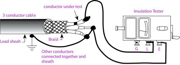
A megohmmeter usually is equipped with three terminals.
- The “LINE” (or “L”) terminal is the so-called “hot” terminal and is connected to the conductor whose insulation resistance you are measuring. Remember: These tests are performed with the circuit deenergised.
- The “EARTH” (or “E”) terminal is connected to the other side of the insulation, the ground conductor.
- The “GUARD” (or “G”) terminal provides a return circuit that bypasses the meter. For example, if you are measuring a circuit having a current that you do not want to include, you connect that part of the circuit to the “GUARD” terminal. This is the simplest of the tests.
Why is a Multimeter not Used for Measuring Insulation Resistance?
A multimeter is able measure different magnitudes, including electrical resistance, whose unit is given in ohms. Its operation, particularly to measure resistance, is given by the action of an internal battery (low voltage) that circulates a small current through the resistance being measured or, failing that, the conductor or winding. The value in ohm obtained belongs to the electrical resistance, which causes the current to pass through the conductor and is incremented according to its longitude and section.
On the other hand, a megohmeter, also known as Megger, is often used to measure the insulation resistance of an insulated body. For its operation, it uses a DC generator or a battery, are able generate output voltage values of up to 5000V. The results obtained in the ohm test are related to the insulation resistance, which has an insulated element relating to an active element or a conductor.
Although there is a degree of similarity between both tools, the insulation resistance is mandatorily measured using a Megger (or a similar device), because it’s able to generate a high voltage that creates a moment of stress in the insulation. Insulation resistance is calculated usually in Mega- or Tera-ohms, inclusive
In conclusion, a multimeter measures the electrical resistance of a conductor (coil), while a Megger measures the insulation resistance of an isolated group (two coils relative to mass), something that a multimeter is unable to do.
Types of Insulation Resistance Tests
Short-Time or Spot-Reading Test
In this method, you simply connect the Megger instrument across the insulation to be tested and operate it for a short, specific time period you have simply picked a point on a curve of increasing resistance values; quite often the value would be less for 30 seconds, more for 60 seconds. Bear in mind also that temperature and humidity, as well as condition of your insulation affect your reading.
If the apparatus you are testing has very small capacitance, such as a short run of house wiring, the spot reading test is all that is necessary. For many years, maintenance professionals have used the one-megohm rule to establish the allowable lower limit for insulation resistance. The rule may be stated: Insulation resistance should be approximately one megohm for each 1,000 volts of operating voltage, with a minimum value of one megohm.
Time-Resistance Method
This method is fairly independent of temperature and often can give you conclusive information without records of past tests. It is based on the absorption effect of good insulation compared to that of moist or contaminated insulation. Tests by this method are sometimes referred to as absorption tests.
This test is of value also because it is independent of equipment size. The increase in resistance for clean and dry insulation occurs in the same manner whether a motor is large or small. You can, therefore, compare several motors and establish standards for new ones, regardless of their horsepower ratings.
Insulation Resistance should be done to prevent hazards such as electric shock and short-circuits caused when the insulation in electrical devices, parts, and equipment used in industrial plants, buildings, and other settings degrades over long periods of use.