Leakage current is the current that streams from either DC or AC circuit in an electrical system to the frame, or to the earth or ground, and can be either from the output or input. The current will stream through other pathways such as the human body, if the equipment is not properly earthed. This might also occur if the ground is ineffective or is intruded unintentionally or intentionally.
Why is Leakage Current Measurement Important?
Electrical system usually consists of a grounding technique that offers shield against a shock hazard if an insulation fault occurs. The grounding system comprises of a grounding rod that connects the instrument to the earth. If ever a disastrous failure of insulation between power line and conductive parts occur, the voltage will be pushed to ground. The current that is created as a result of this event will flow, causing a circuit breaker to open or a fuse to blow thus avoiding a shock hazard.
Clearly, a shock hazard prevails if the earth or ground connection is intruded, either accidentally or intentionally. The possibility for a shock might be larger than assumed if there is case of leakage currents. Even in the scenario of no insulation failure, intrusion of leakage currents streaming through the grounding rod still pose a threat of electric shock to somebody coming in contact with the ungrounded system and ground at the same time.
This is a huge concern when it comes to the field of medical applications, where a patient might be the receiver of the electric shock. A shock can be even fatal if the patient is weak or unconscious, or if the current flows to internal organs. The two layered insulation offered in non-grounded equipment ensures protection. The security in this scenario is made sure because both coats of insulation are not likely to collapse together. Nevertheless, the situations that leads to leakage currents still exists and must be taken into account.
Hence, how can you eradicate or reduce the outcomes of leakage current? Measure the leakage current and then recognise the cause.
What is Done During Leakage Current Measurements?
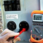
- A meter specially designed for measuring leakage currents is used.
- The current streaming through the ground rod is quantified by attaching the meter in series with the earthing connection.
- For information processing equipment, the ground connection is opened and the current flowing to the neutral side of the power line is measured.
- The meter may also be connected between the outputs of the power supply and ground.
- The test conditions include swapping the ac line and neutral connections, and turning power switches off and on while monitoring the current.
- The test is done once the system have warmed to typical functioning temperature.
- The intention is to identify and measure the worst-case leakage current.
- For very small leakage currents, the meter is substituted with a network comprising of either a resistor or a resistor and capacitor grouping.
- The voltage drop throughout the network is then quantified using an ac voltmeter.
- Double-insulated equipment or ungrounded is verified by attaching the meter amid any touchable conductive part and earth.
- In the case of nonconductive housings, a copper foil of a specific size is placed on the housing, and the current flowing from it to ground is measured.
| Type of Equipment | Maximum Leakage Current |
| Class I | 0.75mA for hand held devices |
| 3.5mA for other devices | |
| Class II | 0.25mA |
| Class III | No hazardous voltages |
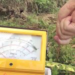
How is Leakage Current Measurement Performed?
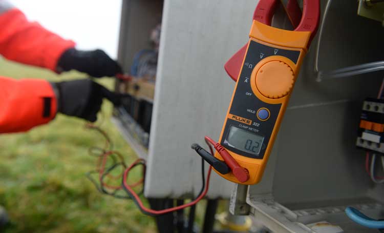
Leakage current clamp meter is used to measure leakage current. They are similar to the clamp meters utilised for finding load currents, but gives considerably better results when quantifying currents less than 5mA. Generally clamp meters wouldn’t register such small currents. After we position the jaws of a clamp meter around a conducting rod or wire, the current reading is taken, and the value depends upon the intensity of the alternating electromagnetic field around the conductor. The clamp meter will identify the magnetic field around conductors like a wire armor cable, single core cable, a water pipe etc. The paired neutral and phase conductors of a single-phase circuit, or all live conductors of a three-phase circuit.
Testing different kinds of conductors:
- When testing the grouped live conductors of a circuit, the magnetic fields produced by the load currents cancel each other out. Any uneven current coming from the conductors to ground is measured with a leakage clamp meter and must have a reading less than 0.1 mA.
- If you performed an insulation test on a circuit that was powered down, the result would be in the range of 50MΩ or further, because the insulation tester utilises s a dc voltage for checking, which do not consider the capacitive effect.
- If you measured the same circuit loaded with office equipment, the result would be significantly different due to the capacitance of the input filters on these devices.
- When a lot of parts of equipment are functioning on a circuit, the result will be collective, that is, the leakage current will be greater and could well be in the range of milliamps. Adding new pieces of equipment to a circuit protected by a GFCI could trip the GFCI. And as the value of leakage current differs based on how the equipment is functioning, the GFCI may trip unintentionally.
- When telecommunications equipment is present, the value of leakage indicated by a clamp meter may be considerably more than that resulting from insulation impedance at 60 Hz because, telecommunications system usually consists of filters that generate functional grounding currents and other gears that generates harmonics, etc.
Measurement of Leakage Current to Ground Conductor
- When the load is switched on, the leakage current measured includes leakage in load equipment. If the leakage is adequately small with the load attached, then circuit wiring leakage is even smaller. If circuit wiring leakage alone is required, disconnect the load.
- If you test single-phase circuits by clamping the phase and neutral conductor, the obtained amount will be any current streaming to ground.
- Test 3 phase circuits by fastening a clamp around all 3 phase conductors. If a neutral is present, it must be clamped along with the phase conductors and the measured amount will be any current flowing to ground.
- To quantity the sum of leakage streaming to the proposed earth connection, position the clamp around the ground rod.
Measuring leakage current to ground via unintentional paths to ground.
- Clamping neutral/phase/ground all together recognises uneven current that means leakage at a passage or electrical panel via unintended pathways to ground.
- If other electrical connections occur like a connection to a water pipe, a similar inequity may occur.
Tracing the source of leakage current
- This series of measurements identifies the overall leakage and the source. The first measurement can be made on the main conductor to the panel.
- Measurements 2, 3, 4 and 5 are made subsequently to identify circuits carrying the larger amounts of leakage current. j k l m n
Leakage current can be a sign of the inefficiency of insulation on conductors. It is achievable to trace the cause of leakage current with the help of a low current leakage current clamp to interpret orderly measurements as needed. If required, this allows you to re-allocate loads all around the installation in a better unbiased manner.