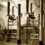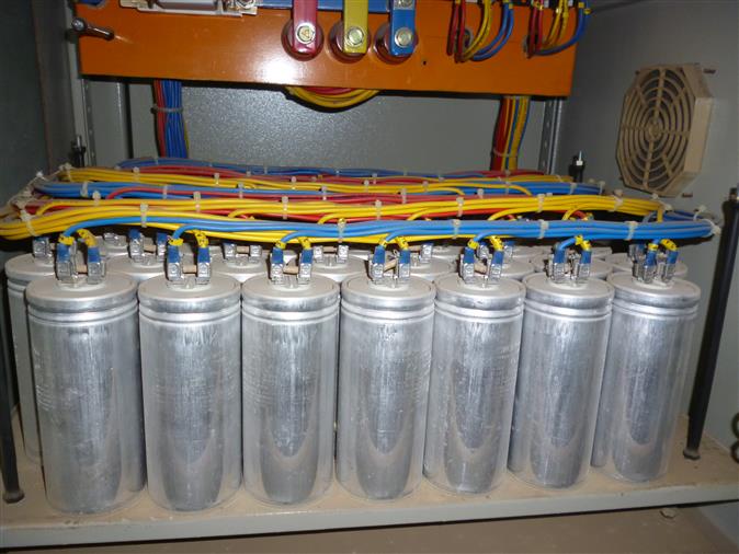
Capacitor Banks consists of tuning reactors, capacitors and inrush limiting reactors. To lower the electricity bill and to decrease shortfalls in the distribution system, power factor correction units or capacitor banks are added to counterbalance as much of the magnetizing current as possible. Capacitors in most power factor correction unit draw current that leads the voltage, thus giving a leading power factor.
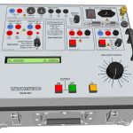
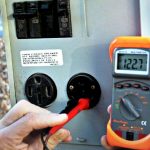
Capacitor bank tests requires test instrument within calibration date, tagged and tested. Insulation resistance tester, Capacitance Bridge, multimeter, three phase balanced voltage source, high speed recorder and single phase current source.
Why is Capacitance Bank Test Necessary?
Capacitors banks performs a vital role in giving your power system proper power factor correction. Power Factor Correction unit have different operating environments dependent on the place they are installed. Moisture, harmonics, temperature and time affects the power factor correcting ability of capacitor banks. Already installed capacitor banks, if not tested or unmaintained within specific time period, becomes incapable of functioning at their finest levels. With time, the operation of capacitors can weaken, decreasing the power factor of your power system, resulting in power factor loss.
Carelabs provides you with comprehensive capacitor maintenance services, making sure that your capacitor banks is functioning to the best of its capacities. Carelabs offers testing for a variety of capacitors, comprising fixed capacitor banks and automatic capacitor banks
What is Done During Capacitor Bank Testing?
There are 3 types of tests in the testing plan. They are:
Routine test:
- Visual examination
- Sealing test at 800C + 50C for 3 Hours.
- Test for output and capacitance.
- Insulation resistance test.
- Voltage test between terminals:
- Voltage test between terminals and container:
- Voltage test between terminals and container for capacitor banks
- Test for efficacy of discharge device:
- Measurement of tangent of dielectric loss angle (tan) :
Type test:
- High Voltage Impulse Withstand Test.
- Bushing Test.
- Thermal Stability Test.
- Radio Influence Voltage (RIV) Test.
- Voltage Decay Test.
- Short Circuit Discharge Test.
Pre commissioning or Installation Test of Capacitor Bank:
- Capacitor bank when introduced at site, should undergo some explicit tests to make sure that the connection of the bank and each unit are in proper sequence and according to specified standards.
How is Capacitor Bank Test Performed?
Site Risk Assessment
- Before performing the tests, any danger or hazards associated with the tasks at the worksite should be recognised and assessed with suitable control measures employed and documented. If any risks cannot be managed or reduced to an acceptable level, do not proceed with the task and seek assistance.
- All the tasks must be performed with capacitor bank de-energised and proper control measures in place to avoid unintended contact with live plant or penetrating exclusion regions.
- After the assessment issue a test Permit
Carry out Secondary Isolation
- Evaluate the requirement to carry out secondary isolation of the protection systems associated with the capacitor bank.
- Factors like sensitivity of capacitor bank protection and the potential for a capacitor under test should be considered to involuntarily discharge stored power into a protection system.
Record plant details and identification details of each capacitor unit:
- Manufacturer’s name
- Manufacturer’s type description
- Manufacturer’s serial number
- Year of Manufacture
- Rated Capacitance Cn and measured capacitance as stamped on the nameplate
- Serial number of each capacitor can
- Rated Output Qn
- Rated Voltage Un
- Rated Current In
- Temperature Category
- Dielectric Fluid Record identification details of any inrush limiting or tuning reactor
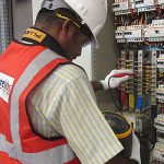
Visual Inspection of Capacitor Bank Condition
- Inspect the external surfaces and ensure the capacitor units and reactors are clean and dry.
- Check that primary connections are correct.
- Check earthing to capacitor bank mounting frames and enclosure.
Measure Insulation Resistance
- Insulation resistance tests are to be applied for one-minute duration each.
- Where several components are connected in parallel, for example capacitor cans, it is not necessary to obtain a separate insulation resistance measurement of each component.
- To make sure that the capacitors being measured have charged enough to permit precise insulation resistance calculation make sure that the capacitor has been charged by the tester such that there is no more than a 5.0% change in insulation resistance over a 1 minute time period.
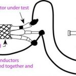
Measure Capacitance
- Measure the capacitance of each individual capacitor unit using a capacitance bridge.
- It is advised not to detach capacitor units for measurement so as to elude involuntary damage to the capacitor unit bushings
- Alternatively, an AC current source may be connected to inject into a capacitor units in series and the voltage measured across each unit from which the capacitance can be calculated according to the formula:
- C = I / (2 x Pi x f x V)
- Where C = capacitance in farads. V = induced voltage in volts. I = injected current in amps. f = frequency of injected current.
Carry out High Voltage Test
- High voltage DC and AC test may be required at the discretion of the commissioning engineer when a de-commissioned bank is being returned to service.
- A capacitor shall withstand a DC Test voltage applied for 10 seconds between the primary terminals.
- The voltage level to be applied is:
- Utest = Un x 4.3 x 0.75
- Where Utest = applied test voltage. Un = capacitor rated voltage.
- Following the high voltage test, repeat the insulation resistance measurement to confirm insulation integrity.
Check balancing of each bank
- By entering the measured capacitance values for each can into an appropriate balancing programme perform a check of the balance of each bank.
- Where necessary, swap cans to achieve acceptable balancing of the bank.
Primary Injection:
- Apply a balanced 3 phase source to the input terminals of the bank and measure:
- The voltage applied to each phase (phase to phase and phase to neutral).
- Each phase line current.
- The voltage of the capacitor bank star point relative to neutral.
- The voltage/current measured at the out of balance protection.
- The secondary current from each metering/protection CT core.
- Confirm that any out of balance current/voltage, when scaled from the primary injection test voltage to actual rated voltage, is below the threshold required for an out of balance alarm or trip to occur.
- Rebalancing of the bank may be required if the out of balance current/voltage is excessive.
Complete Capacitor Bank Pre-commissioning Checklist
A capacitor bank being placed in service for the first time requires that the following items are checked prior to energization:
- Check sheet metal work is free from transport damage and assembled correctly.
- Check that all permanently fixed panels are properly bolted in position.
- Check all door fittings are tight and that the doors swing freely and close and seal securely.
- Check door locks operate properly.
- Check overall appearance and paintwork is clean and free from scratch marks.
- Check the unit has been installed correctly to prevent vermin access.
- Check all control cable terminations are correct and tight.
- Check capacitors and bushings are clean and free from damage or leaks.
- Check that busbar connections have been torqued correctly.
- Check that capacitor bushing connections have been torqued correctly.
- Check earth connections from main earth to cubicle.
- Check all doors and covers have earth strap fitted.
- Check cubicle lighting operation.
- Check the heater operation.
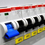
- Check all fuses/links are in place
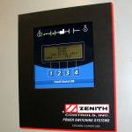
- Check operation of all control and protection functions.
Energise and carry out on-load tests
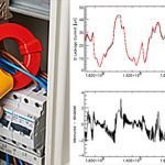
- After energization, record secondary voltages and currents (magnitudes and phase angles) on all protection and metering secondary circuits, including phase, residual and out of balance measurements.
- Prove and record correct operation and adaptivity of point on wave switching devices. Several test energising may be necessary.