Carelabs is authorized provider of Electrical Installation’s Study, Analysis, Inspection, and Certification services in UAE, and provide Automatic Transfer Switch Testing Service.
Automatic Transfer Switch tests, tests utility power or standby generator power, and conducts the power to critical loads. The NFPA, Joint Commission on Accreditation of Healthcare Organizations (JCAHO), and all major ATS manufacturers publish literature calling for the monthly test of ATSs, yet many facility owners ignore these guidelines and refuse to perform the tests. There are good reasons for both the monthly-test requirement and for the reluctance of many operators to comply.
Some people mistakenly think that monthly tests will shorten the life of a transfer switch, and are therefore reluctant to conduct them. More often, the reason for refusing to test properly is a fear of the two brief interruptions in power that an ATS test entails. There’s no truth to the idea of a regular test shortening the life of an ATS. Any device to be used as a transfer switch—switching a single electrical load between two sources of power—must comply with UL standard 1008, the only standard applicable to this duty.
Why is Automatic Transfer Switch Testing Necessary?
The automatic transfer switch (ATS) is a critical system component of the emergency power system, and proper maintenance of an ATS depends on the type of switch and its position in the critical power infrastructure. It is essential to find out whether your ATS is within manufacturers specifications during a planned examination, so that you don’t run the risk of finding this out during an unforeseen outage and you are unable to switch your system to its secondary power.
Intermittent testing of your ATS is the sure-handed method of guaranteeing that your emergency system is as reliable as it can be. Our core group of technicians and engineers have been thoroughly educated and trained on emergency systems, particularly transfer switches. Combining our staff’s training with their vast experience in the field allows for an undeniable recipe for success, where our customers always seek out our expertise and services.
Three Primary Reasons Why Monthly Automatic Transfer Switch Test is Required
- A test is an active demonstration that the ATS is still able to function as intended.
- An automatic transfer switch is an electromechanical device with moving parts. Like the pistons and crankshaft in an automotive engine, the moving parts in an ATS can seize if they’re left in one position for months or years. Regular exercise will help ensure that moving parts will continue to operate smoothly.
- A transfer switch test transfers building load onto the generator for the duration of the generator test. Most standby power generators of more than 100kW are diesel engine driven, and all major diesel generator manufacturers recommend a load of at least 50% of maximum capacity during monthly generator tests. NFPA requires the same thing, for the simple reason that running under a light load is very bad for a diesel engine.
What is Done during an Automatic Transfer Switch Test?
Following Steps are Performed
- Simulate loss of normal power.
- Return to normal power.
- Simulate loss of emergency power.
- Simulate all forms of single-phase conditions.
Carelabs ATS Testing Checks Include
- Check wiring and connections are tight with no discoloration of metal, melted plastic and odour indicating excessive heat.
- Verify external operating mechanism is clean and re lubricate if found dirty
- Check for any deterioration of wiring insulation such as cuts and abrasions. Replace or repair any damaged wiring.
- Check tightness of wiring connections. Re-tighten to specification if any loose wiring found.
- Perform insulation resistance tests on all control wiring with respect to ground.
- Perform a contact/pole-resistance test.
- Verify settings and operation of control devices.
- Calibrate and set all relays and timers.
- Verify phase rotation, phasing, and synchronized operation as required by the application.
- Check ATS main power switching contacts condition. Clean or replace. Replace contactor assembly if necessary.
- Exercise the generator set under load.
- Test the transfer switch’s automatic control system.
- Test all indicators (LEDs) and all remote control systems for operation.
- Inspect the outside of the transfer switch for any indication of wear, excessive vibration, leakage, high temperature, contamination or other deterioration.
- Verify all external components are in place, firm, tightened and not excessively worn.
- Inspect the inside of the transfer switch for any indication of excessive vibration, leakage, high temperature, contamination or any other deterioration.
- Verify all internal components are in place, firm, tightened and not excessively worn.
How ATS Testing is Done?
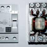
ATS is a pretty simple device. It senses power source and behaves according to how it’s set up. Generally it defaults to generator, so with no power all 3 contacts, (30 amp) or 4 contacts, (50 amp) should measure closed and electricity will pass from one contact to the other.
Carelabs process of acceptance testing and maintenance testing standards for your ATS are based on NETA Acceptance & Maintenance Testing Standards.
Automatic transfers should operate in accordance with manufacturer’s design. A general procedure for functional testing of an automatic transfer switch and standby generator is described below.
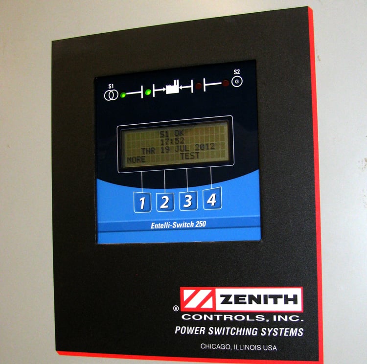
- To begin the test, the normal source circuit breaker is closed. The switch controller will illuminate the Utility Available LED (if equipped) when correct voltage is sensed. If the ATS mechanism is set on Source 1, the Source 1 position LED will also light. The phase to phase voltages at the utility line terminals is verified.
- Next, the Alternate source breaker is closed and the engine generator is started. The S2 (Alternate) Available LED will illuminate when correct voltage and frequency levels are sensed. After both sources have been verified, the engine generator is shut down, and the generator’s start control is put in the automatic position.
- A utility outage is generated by opening the Source 1 (normal side) breaker. The delay to engine start timer begins its timing cycle. After the timer has completed its timing cycle, the engine start contacts close to start the generator.
- When generator voltage and frequency reach the preset restore points the Source 2 Available LED illuminates. Simultaneously, the delay to generator timer begins its timing cycle. When the time delay is completed the ATS will transfer to Generator, the S1 position LED goes off, and the S2 position LED illuminates. Systems shall transfer in no less than 10 seconds where failure of the equipment to perform could result in loss of human life or serious injuries.
- Source 1 breaker is closed again to re transfer to the normal source. The delay to utility timer begins its timing cycle. When the timer has completed its timing cycle, the ATS will transfer. The S2 position LED goes off, and the S1 position LED illuminates.
- The delay engine stop timer will begin its timing cycle. The generator runs unloaded for the duration of this timing cycle. When the timer completes its timing cycle, the generator will stop. The S2 Available LED goes off. A minimum time delay of 5 minutes is provided for unloaded running of the EPS prior to shutdown to allow for engine cool down (NFPA 110). The minimum 5-minute delay is not required on small air-cooled prime movers 15 kW or less.
A field testing label is applied in accordance with NFPA standards indicating that the transfer switch is electrically and mechanically sound and suitable for service after completing all tests.
Whether you are looking for routine maintenance, or wanting to troubleshoot ATS failure or have emergency systems queries, contact Carelabs. We offer monthly, quarterly and semi-annual inspections and testing.